Development Support for TESLA 3000 MPB

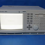
The TESLA 3000 MPB was developed for NxtPhase by Fidus in Ottawa.  It went fairly well, until the prototype board would just not recognize the Ethernet NIC, at all.  Michael Miller asked Elecsys to investigate.

I insisted that we boot LINUX on the board.  Fidus advised that it was not feasible to do so.  I persisted, and after about a week’s work (customizing the boot parameters and hacking the kernel a bit), I had it booting to LINUX with a small laptop hard drive.  Sure enough, the Ethernet NIC would not come up, even though it was fully supported by the installed LINUX driver.

By instrumenting the driver with printk() and observing the result of loading and unloading the driver in the system log, I determined that it was a short between two lines on the PCI bus to the NIC.  When Fidus took a close look at the Gerber files, they discovered that the design rules were too tight on the PCI bus on a deep inside layer of the PCB.  The PCB was corrected and remade, and the NIC worked.

Later, there was an issue with the operation speed of the MPB core.  Fidus was doing the FPGA development in VHDL on Synopsys, but did not have the resources to continue.  I took over the development under Synopsys, having to establish VPN to Fidus to obtain the license for it to run.  I suspected that the Synopsys tools, as good as they were, could be responsible for my inability to get appropriate performance from the FPGA.  I ported the VHDL out from Synopsys back to Xilinx ISE, a byproduct of which was that we could do full development stand-alone in Winnipeg, which was nice.

With a few tweaks, I was able to get the MPB FPGA to simulate out at better-than-required full speed operation, which was proved out in actual operation.  I mapped a path to higher speed operation, anticipated as a requirement for future product development.

Developed TESLA 3000 Analog Input Board (AIB)

The TESLA 3000 was designed to put the analog-to-digital conversion as close as possible to the rear panel, so the AIB had 6 x TI ADS8364 6 channel 16 bit SAR ADCs on it, with the associated front end and conditioning circuitry. A Xilinx Spartan 3 FPGA directed the acquisition timing, collected the ADC data, and communicated with the TESLA 3000 MPB using a bidirectional high speed LVDS synchronous serial link.

I did the architecture and design of the TESLA 3000 AIB, and oversaw the PCB layout by an external contractor.  I specified the operation of the FPGA, how it interfaced to the MPB, and how it was programmed for operation.

The FPGA firmware was developed in Verilog on Xilinx ISE by a contractor at Fidus in Ottawa.  When that FPGA developer was unable to complete the job, I took over and finished the project.

Developed the DR2/TESLA Main Processor Board (MPB) and Other DR2 & TESLA Boards

I used to say, “those aren’t electrons flowing on the MPB, those are my blood cells!”   In a philosophical sense, it was true – the development of the MPB drained me like no other project effort, before or since.

With multiple processors on board – 2 x PIC 16C MCUs (one for front panel keyboard, one for watchdog processor), a TI TMS320C32 DSP, an Altera Flex 10K FPGA, an Altera MAX 7000 CPLD, 3 x National Semiconductor LM12458 microsequenced ADCs, and a Motorola MC68HC11 MCU for IRIG processing, 3 x NS16550 FIFO UARTs, and a 16 bit PC-104 bus connection, it was quite busy.  An X86-based PC-104 card was mounted on top of the MPB – lower powered on the DR2, but much more powerful model on the TESLA.

The concept was that sifting, sorting, compression, and decision making was done on the DSP, where memory was expensive but calculations were easy.  The resultant data was streamed through a high-speed DSP-to-X86 FIFO, where the X86 DMA’d it into main memory and stored it to disk.  The X86 was used because its memory was plentiful and inexpensive, and disk I/O was fast and easy.

The other boards in the system weren’t as complex, but were just as important.  The DR2 AIB, mounted on the bottom of the chassis, had up to 18 miniature PCB-mount instrumentation transformers on it – CTs or PTs, depending on the application – and analog processing to transfer to the ADCs on the MPB.  The TESLA AIB was mounted on the rear of the chassis, had more channels but was less sophisticated – non isolated +/- 2.5V (nominal) input.  The DR2 and TESLA each had their own interpretation of digital I/O – DR2 with high current relay outputs, and dedicated ultra reliable digital inputs, and the TESLA with fewer and lower level outputs and simpler digital inputs.

The front panel of the DR2 had a 2 line x 24 character FIP display, a small keyboard, and several indicator LEDs, including a large bright red “Target” LED, as is expected on a relay.  The TESLA front panel had the smaller LEDs only.

I established the bus structure and pin-outs for all the I/O.  The front panel and digital I/O were intentionally designed to be interchangeable, with the intention of future mixed mode configuration, or expansion.  Although some of the buses had extra connections (front panel serial port, for instance), this was kept to the ends of the connectors, so combining and splitting ribbon cables would be relatively straightforward.  This was very well documented in extensive spreadsheets, which clearly showed connections and levels.

The memory and I/O maps of the processors was also documented in spreadsheets, with well defined bit states and clearly defined defaults.

Later, I wrote an exhaustive 70+ page programming guide to the MPB, which outlined all its features, how each processor interacted, the resources used, assumptions in programming, and how to compose images for execution.

Developed the Conviron Integrated Logger Controller (ILC) Card

The CMP3000 has a very sophisticated network operating over isolated RS-422 signals in a ring-bus arrangement.  Each controller has a bypass relay which would heal the ring-bus in the event of controller or communication board failure.  The Zilog Z8530 Serial Communications Controller (SCC) chip was used to talk HDLC on the ring-bus.

The master of the network was the CMP3300 Data Logger Processor (DLP), which was essentially a hot-rodded CMP3000 controller with different programming.  It could manage and control up to 96 CMP3000 controllers on its loop.

To enhance and extend its function, the DLP had a serial port which could be connected to the Host Computer, an IBM PC running QNX.  The Host computer could be connected to 3 DLPs, allowing it to manage many more controllers.

Being a general purpose PC running QNX, the Host Computer was able to schedule changes, log all kinds of data, display graphs, and export data to other media (think: floppy disks!).

There came a time when the DLP just seemed clunky.  So, I was asked to create the Loop Control Card (LCC), which would mount directly into the IBM PC chassis and replace the DLP.  It would be able to control 3 loops of controllers, and have embedded on-board alarm contacts.

By then, the PC of choice was the AT, and Vansco actually was making its own labelled computers, based on components purchased overseas.  However, the LCC was designed for the XT bus for maximum compatibility.

The heart of the board was a NEC V25 processor, high-speed (well, for the time) SRAM, and a few PLDs, where I implemented a pseudo-dual-port RAM for control and data transfer.  Internal bus faults occurred periodically, which proved almost impossible to track down without the right test equipment.  Finally, management went and bought a very expensive (at he time) Fluke/Phillips PM3585/90 logic analyzer, which I proceeded to load up to the maximum, using its dual timing & state analysis to great advantage.  In the end, the V25 was every once in a while stealing an extra clock cycle for its prefetch queue, causing a bus timeout.  The PC bus specification wouldn’t let me stretch it any further.  I was able to rework the logic and make it all come together.  You gotta have the right tools!

PM3585 Logic Analyzer

Developed the Kodiak Scoretec Ultimatic U1000 Scoreboard Controller

Initially, Kodiak came to Vansco to fix a problem on their previously-developed MOS 6502-based shot clock.  There was some kind of a bug in the code, and all they had was a paper listing.  They didn’t even have the binary, just a working EPROM!  I found the bug, rolled out the EPROM to disk, patched it in binary with a jump to a previously unused area, and gave them the binary to program future systems.  All in about 24 hours.  They were pretty impressed, so they brought a project to us for the development of their next generation system.

The previous generation was functional enough, but had a huge circuit board with hard-wired digits.  We were tasked with coming up with an easier-to-service, more modular system.

I selected the NEC V25 processor as the core of the design, and an Optrex 24×2 line alphanumeric display.  We used simple Omron B10 switches for buttons, behind a custom screened Lexan overlay – which would be changed for different games.  The software would generally change too, of course.

The large scoreboard panel operated on wall outlet power, of course, which was stepped down for operation of small 12V incandescent lamps.  The panel used an MC68705 processor programmed by Mike Stasenski, decoding a synchronous data stream sent by the keyboard unit.

The key innovation here was that the panel boards could be daisy-chained to arbitrary length, allowing for flexibility in panel design.  Smaller panels could be made less expensive by leaving off the later units in the chain – well, of course, we selected those panels that would be optional to be later in the stream.  Hmm, actually the data came out first in the stream, so that it would shift “off the edge of the world” on units not equipped with the extra digits.

John Janiw was the brilliant mind behind the layout and operation of the keyboard.  He knew so much about all the games, their rules, and how to make the operation intuitive!  Frank Herzog did the programming, actually compiling the code in QNX 2 but targeting for the bare-metal operation of the keyboard’s V25.

Frank and Mike later left the company, and I was the only one on the development team left, so I was supporting this product, both hardware and software, to the end of its life.   The last work that I did on it was in 2006, while Jason and I were operating our consulting company, Elecsys Solutions.

Developed Transformer Winding Controller model 114000

This was the last in the series of transformer winding controllers developed for Micro Tool and Machine.  It was an amazing work of their craftsmen!

The main mandrel was driven by a large stepper motor, giving fine pitched accuracy on the winding.  There was a second, smaller stepper motor driving a traverse that payed out the wire onto the mandrel,  moving left to right on a lead screw.

The mandrel and traverse stepper motors made characteristic sounds as they indexed, accelerated and decelerated, giving the machine a unique personality.

There was a tap forming head above the mandrel which moved with the traverse head, through which the wire passed.  At a given point, the mandrel would stop, clamps would come down onto the wire on either side of the tap former, a clamp wrapped the wire in the middle, then twisted 2 complete turns as it pulled up – while the clamps on either side, operated with pneumatics, would slide in.  This formed a perfect wire tap, where a long bolt could be passed through to the top of the transformer.

The placement of the wire tap was critical, otherwise the tap bolt would not line up with the insulator and hole in the casing.  I took very careful measurements of all aspects of the machine, then worked the math so that I could determine exactly how far ahead to stop the mandrel to make the tap, and then have it wind down to the correct spot.  As the rotation speed of the mandrel was well known (and set by the controller using a stepper motor), a payout encoder on the wire at the tap former gave constant information for the circumference of the winding.  From this, and knowing the geometry of the machine, the exact point that the mandrel had to decelerate and stop, could be calculated.   The amazing thing was – it worked!

The last cool feature of this machine was duct tap insertion – a compartment of insulating rods was kept on the side, and could be pneumatically pushed up into one-way catch slots on the ends of the winding mandrel.  This provided spacing between layers, or between windings.

All of this made for a fantastic sight.  Almost autonomous transformer winding!  Although the operator was still required to baby-sit the machine, in case anything went wrong.  Of course, they had to change wires for LV and HV (LV wire was more like a wide copper foil), weld to the ends (propane welding of copper!) and tie off things when appropriate.

I was so enthused about it, that I borrowed Lorne’s camera and made a video of it in operation.  I’ll have to dig up that tape, digitize it and post it sometime!

The machine had multiple processors on multiple boards, coordinating all this activity.   The traverse controller was implemented with a Motorola MC68701, programmed by Lorne and by me; the tap forming controller was implemented with a Motorola MC68705U5, programmed by Mike Stasenski, and I did the programming on the MC6800 on the main controller, coordinating all their activities.  I designed the “piggyback board” which contained the very-cool PCL-240K stepper motor controller for the mandrel, the “traverse board” and the “connector board” where all the different boards wired to for the interchange of communications.

This machine went to Delta Transformers in St. Jean-sur-Richelieu, Quebec.  In 1988, I visited the plant and saw my machine in action.  The engineer responsible for the machine, Guy Desormeaux, told me that the company had recently been acquired, and that this transformer winding machine was fiercely sought after!

Developed Transformer Winding Controller model 109000

This was one of a series of transformer winding controllers developed for Micro Tool and Machine.  It used an variable speed eddy current clutch with induction machine drive.  As part of a three-person development team, my responsibility was for the electronics, and for the main controller software development.  Like the CMP3000 and other Micro Tool systems, the main controller of the model 109000 was a Motorola MC6800.

Developed Fully Mitre Transformer Core Shear Controller

One of a number of controllers that Vansco developed for Micro Tool and Machine, my thesis partner Danny Lew and I took on the development of the Fully Mitre Core Shear Controller as our undergraduate thesis.  We built upon the existing software and main controller board, but had to modify the programming to accommodate left/right/angle stops on the head rotation, distance measurement on the material progression, and control of the material movement, shear rotation and closure, and punch activation.

I did a PCB layout (double sided tape on mylar – that was some time ago!) for the I/O board – incorporating multiple options, including some that we weren’t able to use – several of the boards were manufactured.  I kept one as a momento.

We were just wrapping up the project when the blizzard of final exams hit, so the my manager Lorne Repas did a chunk of the finishing work.  Overall, I was very proud of the result!

Like many Micro Tool and Machine controllers, we hoped that there would be repeat orders, but to my knowledge, we only built the one.  I’m pretty sure Micro Tool would have liked repeat orders too, but it just seemed that we were always doing one-offs.  That’s life.