

I’ve been playing, on and off, with IRIG-B decoding – first, modifying NTP source code to continuously dump decoded data from what it reads on the audio input port… then extracting the IRIG-B decoding code to a stand-alone program which would read from the audio input port and output decoded data… then added unmodulated IRIG-B decoding (which was a challenge, due to audio bandpass limitations, but I made it work)… then putting it to an LCD display, then another, then another with keypad…
Through it all, I struggled to find a practical way of making it useful. After a discussion with Norbert of ERLPhase, I think maybe we came up with something.
Mobile Device Use?
Rather than expect someone to load up LINUX onto their laptop, drag the laptop to the site where the IRIG-B source is, and use a special cable to connect to the audio input port… why not use the mobile device that everyones seems to carry around with them?
I briefly tried to capture the IRIG-B signal (modulated and unmodulated) into a mobile device, without success 🙁 I tried both my Samsung Galaxy S5 (SM-G900T) and my Samsung Galaxy Tab S2. No luck. Maybe my physical setup might have been a bit precarious – I found out later that my audio jack connection may have been suspect – but, the result, even when it did seem to get signal, was not good. A severely attenuated low frequency response (basically gone below about 100 Hz) made it almost impossible to decode the audio captured by either device.
Create a USB OTG Device?
Having used the Silicon Labs‘ Universal Bee EFM8UB2 processor last year while working at ERLPhase, and after talking to Norbert… why not capture the IRIG-B signal on the USB2’s analog input port, and then funnel it to any customer’s mobile device through the UB2’s well-integrated USB port? After all, most modern Android devices support USB-on-the-go, where the mobile device can act like a USB host (similar to a computer) or a USB device (similar to a USB flash drive, camera, or MP3 player).
I thought maybe the EFM8 could do simple 8 ksamples/second signal acquisition (the sample rate used by NTP and later read_irig programs), then send packets of data to the mobile device, where it would be saved to a file that would be submitted for post-acquisition analysis. This way, the burden of processing would be moved from real-time to remote post-acquisition, maximizing the likelihood of successful data capture.
Universal Bee Development Kit
I acquired the SLKSTK2001A Universal Bee EFM8 UB2 Development Kit and played with the examples.
Oscilloscope Example
The SLKSTK has a neat little graphical LCD display and a few buttons on it, and one example supplied was a simple oscilloscope program EFM8UB2_Oscilloscope which could acquire data on an analog input at 24 to 500 ksamples/second. I created a custom version of this software locked at a sample rate of 8 ksamples/second with favourable amplitude and trigger settings. I was readily able to see unmodulated IRIG-B waveforms! Unfortunately, the EFM8 device only does unipolar conversions, and SLKSTK doesn’t have any circuitry to enable bipolar input – so modulated IRIG-B would only show half cycles.
I introduced a crude offset by wiring a 47k bias resistor to the analog input from the 3.3V supply bus. Together with the 10k-22k-10k divider chain on the input, this gave a reasonable DC offset, so both modulated and unmodulated IRIG-B could be seen.
VCPXpress Echo
A second example supplied was a program to emulate a Silicon Labs CP210x serial port on the USB interface, EFM8UB2_VCPXpress_Echo, which performed a simple reflection echo of characters sent out.
To prove that it was working, and not just a local echo from minicom – ugh sometimes minicom frustrates me – I modified the Echo program to echo every character twice, then follow every character with an arbitrary string “Burp!” and carriage return. It took a bit of doing, but it worked.
Oscilloscope with added VCPXpress USB Transmission – Failed
Well, I had the 8 kS/S data acquisition in my modified Oscilloscope project, so I mashed it together with the VCPXpress libraries… and got crap. It seems as thought the whole thing messed up the link process so badly that symbols resolved, but overlapping memory areas caused unpredictable behaviour… and it would not run. There was just too much gratuitous complexity in the Oscilloscope project. So, I thought I would work the problem from the other end.
Starting with VCPXpress
I started with EFM8UB2_VCPXpress_Echo, putting out canned strings. I wrote a simple Python script on my LINUX machine to accept the strings. That worked.
I added framing and a packet structure to the strings, and decoding into the Python script. That worked too.
I had thought that I’d send the full 10 bit ADC values, packing them as needed into the serial stream. However, the nominal line rate is 115 kbaud, or about 11,500 characters per second. Sending 8 kS/S of 10 bit data would take 10,000 bytes per second. With 5 bytes of overhead per packet, and 50 bytes of data per packet, then this 10% overhead would result in 11,000 bytes per second, not enough margin to make me feel comfortable that it would be a robust transfer.
In fact, I decided to add 2 more bytes of overhead per packet – a running binary sample count, to tell if overflow or underflow had occurred – so the overhead is now 14%.
Now, the original NTP code only used 8 bit samples, and seemed to work just fine. So, why not reduce the data size to 8 bits per sample? Then 8 kS/S of data would be 8,000 bytes per second, and with 14% overhead, still “only” 9,120 bytes per second.
It turns out that the 115 kbaud line rate is conservative, and really only even supported to make legacy software happy – the USB connection is far faster than this, and will transfer much more data than the stated. So, in the end, with 8 bits per sample, the link is very solid.
Here’s the packet format:
00 --------- SOH
01 --------- TYPE - Echo of Command (presently fixed)
02 --------- DATLEN - Data Length (binary)
03 -------+
 .        +- DATLEN bytes of binary data
 .        |
DATLEN+2 -+
DATLEN+3 --- CKSUM - sum TYPE to CKSUM (inclusive) is zero
DATLEN+4 --- EM - end marker - end of frame
The binary data that I typically send is 52 bytes total, including 50 bytes of analog data:
00 --------- Acquisition Count High Byte
01 --------- Acquisition Count Low  Byte
02 --------- First Data Sample
 .
 .
DATLEN-1 --- DATLEN-2th Data Sample
Data Acquisition and Transmission
I added data code to make the 8 kS/S ADC acquisition, directly timer driven for jitter reduction, interrupt at the end for buffer stuffing. The data was reduced from 10 bits to 8 bits at interrupt level. Two swing buffers were employed, with main line code creating the packet and firing it off to the VCPXpress code for transmission.
Python Processing
Data Reception and Processing
I modified the Python script to receive the analog samples and stuff them into a list, keeping track of whether packets were valid and all samples were present, then writing them to a CSV for processing in a spreadsheet. I was able to verify that the data was transferred intact and complete, with reasonable fidelity.
I then proceeded to decode the unmodulated IRIG-B signal bits as (0/1/Position Indicator/Invalid), and add them to the CSV file output. Then, I decoded the signal bits and compose a string of characters to represent each one-second frame of IRIG-B data. Lastly, if the frame met proper format criteria (PIs in the right places, 1/0s in the right places, not too many bits), I pulled the data out and performed full decoding just as I had done with read_irig in the past. I also added this to the CSV file output.
I actually created three CSV file outputs:
- Raw data sample file – with extended columns for bit decode internal data
- Bit decode sample file – each bit as it was decoded – with extended column for full decode output when successfully performed
- Full decode file – a bit string for each one-second frame, plus fully decoded data
Threshold Detection
It was difficult to consistently get good thresholds for decoding, so I added rescaling. The maximum and minimum values of signal in the file are calculated. An offset is subtracted to centre the signal around zero, then a gain is multiplied to make the signal approximately -3 dB of full scale, or about +/-25,000 counts.
Modulated IRIG-B Processing
It was difficult to decide how to work with modulated IRIG-B. The original NTP code did a kind of phase-locked loop decode on the signal, so it could recover the bit stream, but also the precise zero cross time, so the local clock could be time sync’d to the IRIG-B signal. I didn’t want to do this. The code is hard to understand, we don’t need time sync for post processing, and I’d rather not incorporate someone else’s code if I don’t have to.
Instead, I went back to the way that Filipe and I designed modulated IRIG-B processing so many years ago: watching for positive side pulses due to the sinusoid going above zero (Polarity), and also for “high” level amplitude by positive side pulses due to the sinusoid going above a threshold (Peaks). Polarity without Peak means low level cycle, Polarity with Peak means high level cycle.
One problem was an unknown baseline. As mentioned, an arbitrary offset had been applied. The maximum and minimum values of signal in the file are calculated. Zero cross was assumed to be at the halfway point – the median – the average of maximum and minimum – this gives Polarity.
The amplitude of a low level cycle is defined as 1/3 the amplitude of a high level cycle. The threshold would be halfway between these two levels, or 2/3 the amplitude of a high level cycle, or 5/6 of the way to maximum level –
minimum + (5/6 x (maximum – minimum))
Now, I tracked how many high level cycles in a row happened before low level cycles resumed. This would determine whether a bit was a 0/1/Position Indicator.
Tarball and Steganography
I added a feature to roll the three CSV files up into a GZIPped tarball. Because the files are ASCII, they compress well. Then the original CSV files are deleted. A tarball is easier to transfer for post processing.
A tarball might not pass E-mail inspection, so I added a steganography library to encode the tarball into an arbitrary JPEG image. The JPEG image would likely get through the E-mail system more easily. However, this processing took a very long time (over 10 minutes) and created a huge image file (original 100k, over 5 Meg afterwards), so this was abandoned.
Improvements
Automatic Gain Control
By putting the EFM8 MCU’s VREF on an RC-integrated PWM output, and using the same signal as a DC bias offset on the analog input, I could change the bias and the ADC span under program control.
I added code to the EFM8 to track the maximum and minimum ADC input levels (single ended) and calculate whether the system gain should be increased or decreased to make the span approximately 128 counts, or about half scale. Margin is maintained, but gain is maximized. The system is designed to track within a second or two of amplitude change.
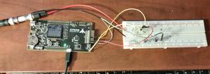
Building it Onto a Beadboard
The analog circuitry was put onto a breadboard and wired to the EFM8 MCU on the development kit.
Next Up
Next, to connect this to a mobile device, invoke a serial port driver, and capture the data there for post processing analysis. That’s easier said than done!