Developed the Conviron Integrated Logger Controller (ILC) Card

The CMP3000 has a very sophisticated network operating over isolated RS-422 signals in a ring-bus arrangement.  Each controller has a bypass relay which would heal the ring-bus in the event of controller or communication board failure.  The Zilog Z8530 Serial Communications Controller (SCC) chip was used to talk HDLC on the ring-bus.

The master of the network was the CMP3300 Data Logger Processor (DLP), which was essentially a hot-rodded CMP3000 controller with different programming.  It could manage and control up to 96 CMP3000 controllers on its loop.

To enhance and extend its function, the DLP had a serial port which could be connected to the Host Computer, an IBM PC running QNX.  The Host computer could be connected to 3 DLPs, allowing it to manage many more controllers.

Being a general purpose PC running QNX, the Host Computer was able to schedule changes, log all kinds of data, display graphs, and export data to other media (think: floppy disks!).

There came a time when the DLP just seemed clunky.  So, I was asked to create the Loop Control Card (LCC), which would mount directly into the IBM PC chassis and replace the DLP.  It would be able to control 3 loops of controllers, and have embedded on-board alarm contacts.

By then, the PC of choice was the AT, and Vansco actually was making its own labelled computers, based on components purchased overseas.  However, the LCC was designed for the XT bus for maximum compatibility.

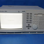
The heart of the board was a NEC V25 processor, high-speed (well, for the time) SRAM, and a few PLDs, where I implemented a pseudo-dual-port RAM for control and data transfer.  Internal bus faults occurred periodically, which proved almost impossible to track down without the right test equipment.  Finally, management went and bought a very expensive (at he time) Fluke/Phillips PM3585/90 logic analyzer, which I proceeded to load up to the maximum, using its dual timing & state analysis to great advantage.  In the end, the V25 was every once in a while stealing an extra clock cycle for its prefetch queue, causing a bus timeout.  The PC bus specification wouldn’t let me stretch it any further.  I was able to rework the logic and make it all come together.  You gotta have the right tools!

PM3585 Logic Analyzer

Design Improvements for Conviron CMP3000 Switching Supply

The power supply for the CMP3000 controller was failing and needed some work. It had a crowbar circuit across its output, to protect the expensive & sensitive downstream control circuitry.  Unfortunately, it would kick in once in a while, sometimes causing the power supply to burn itself up.  It wouldn’t even blow the fuse – just cook itself to death.

Everyone else was busy, so Lorne gave me the job.  I dove into the TL494, its operation, and how our circuit worked.  Amazing!  I mean, I’d been working with simple linear regulators for years, but the idea of discontinuous conduction being able to transform voltages, was a revelation to me.

First, we improved the heat dissipation capability of the main switch transistor by increasing its heatsink area (as I recall, we just stacked an extra one on).  That addressed the immediate problem of circuit damage.

Then, we reduced the fuse rating, but worked hard to ensure that no nuisance fuse operations would occur.

Lastly, Lorne introduced me to the concept of foldback current limiting.  I actually got the circuit operation backward the first time, and sent it into a serious overcurrent,  ha ha.  Then I got it right.  Lorne helped me get it fine tuned, honestly, but I was quite enthused about the result.  No overheating, no fuse blowing, and now fully short circuit proof!

At the same time, I did an parametric analysis of the crowbar circuit, and came up with a better way to trip it with more accuracy & repeatability.

With these changes made, the CMP3000 supply was solid for years, until we later switched it to a MOSFET switch…. someone else did that 🙂

Developed the Kodiak Scoretec Ultimatic U1000 Scoreboard Controller

Initially, Kodiak came to Vansco to fix a problem on their previously-developed MOS 6502-based shot clock.  There was some kind of a bug in the code, and all they had was a paper listing.  They didn’t even have the binary, just a working EPROM!  I found the bug, rolled out the EPROM to disk, patched it in binary with a jump to a previously unused area, and gave them the binary to program future systems.  All in about 24 hours.  They were pretty impressed, so they brought a project to us for the development of their next generation system.

The previous generation was functional enough, but had a huge circuit board with hard-wired digits.  We were tasked with coming up with an easier-to-service, more modular system.

I selected the NEC V25 processor as the core of the design, and an Optrex 24×2 line alphanumeric display.  We used simple Omron B10 switches for buttons, behind a custom screened Lexan overlay – which would be changed for different games.  The software would generally change too, of course.

The large scoreboard panel operated on wall outlet power, of course, which was stepped down for operation of small 12V incandescent lamps.  The panel used an MC68705 processor programmed by Mike Stasenski, decoding a synchronous data stream sent by the keyboard unit.

The key innovation here was that the panel boards could be daisy-chained to arbitrary length, allowing for flexibility in panel design.  Smaller panels could be made less expensive by leaving off the later units in the chain – well, of course, we selected those panels that would be optional to be later in the stream.  Hmm, actually the data came out first in the stream, so that it would shift “off the edge of the world” on units not equipped with the extra digits.

John Janiw was the brilliant mind behind the layout and operation of the keyboard.  He knew so much about all the games, their rules, and how to make the operation intuitive!  Frank Herzog did the programming, actually compiling the code in QNX 2 but targeting for the bare-metal operation of the keyboard’s V25.

Frank and Mike later left the company, and I was the only one on the development team left, so I was supporting this product, both hardware and software, to the end of its life.   The last work that I did on it was in 2006, while Jason and I were operating our consulting company, Elecsys Solutions.

Developed Transformer Winding Controller model 114000

This was the last in the series of transformer winding controllers developed for Micro Tool and Machine.  It was an amazing work of their craftsmen!

The main mandrel was driven by a large stepper motor, giving fine pitched accuracy on the winding.  There was a second, smaller stepper motor driving a traverse that payed out the wire onto the mandrel,  moving left to right on a lead screw.

The mandrel and traverse stepper motors made characteristic sounds as they indexed, accelerated and decelerated, giving the machine a unique personality.

There was a tap forming head above the mandrel which moved with the traverse head, through which the wire passed.  At a given point, the mandrel would stop, clamps would come down onto the wire on either side of the tap former, a clamp wrapped the wire in the middle, then twisted 2 complete turns as it pulled up – while the clamps on either side, operated with pneumatics, would slide in.  This formed a perfect wire tap, where a long bolt could be passed through to the top of the transformer.

The placement of the wire tap was critical, otherwise the tap bolt would not line up with the insulator and hole in the casing.  I took very careful measurements of all aspects of the machine, then worked the math so that I could determine exactly how far ahead to stop the mandrel to make the tap, and then have it wind down to the correct spot.  As the rotation speed of the mandrel was well known (and set by the controller using a stepper motor), a payout encoder on the wire at the tap former gave constant information for the circumference of the winding.  From this, and knowing the geometry of the machine, the exact point that the mandrel had to decelerate and stop, could be calculated.   The amazing thing was – it worked!

The last cool feature of this machine was duct tap insertion – a compartment of insulating rods was kept on the side, and could be pneumatically pushed up into one-way catch slots on the ends of the winding mandrel.  This provided spacing between layers, or between windings.

All of this made for a fantastic sight.  Almost autonomous transformer winding!  Although the operator was still required to baby-sit the machine, in case anything went wrong.  Of course, they had to change wires for LV and HV (LV wire was more like a wide copper foil), weld to the ends (propane welding of copper!) and tie off things when appropriate.

I was so enthused about it, that I borrowed Lorne’s camera and made a video of it in operation.  I’ll have to dig up that tape, digitize it and post it sometime!

The machine had multiple processors on multiple boards, coordinating all this activity.   The traverse controller was implemented with a Motorola MC68701, programmed by Lorne and by me; the tap forming controller was implemented with a Motorola MC68705U5, programmed by Mike Stasenski, and I did the programming on the MC6800 on the main controller, coordinating all their activities.  I designed the “piggyback board” which contained the very-cool PCL-240K stepper motor controller for the mandrel, the “traverse board” and the “connector board” where all the different boards wired to for the interchange of communications.

This machine went to Delta Transformers in St. Jean-sur-Richelieu, Quebec.  In 1988, I visited the plant and saw my machine in action.  The engineer responsible for the machine, Guy Desormeaux, told me that the company had recently been acquired, and that this transformer winding machine was fiercely sought after!

Linearizing the YSI 44030 NTC thermistor for the CMP3000 Analog Input Board

Some things just stick in your memory – like the part number of a thermistor, for instance…  well, maybe not for you, but for me.  Yikes.

In second year, the development of the CMP3000 control system was in full swing.  Mike Stasenski was working on the CMP3521 Analog Input Board.  It was based on the then-relatively-new MC68705U3 single-chip MCU.  It was pretty limited in capability, but of course Mike was (and is) a very capable programmer, able to wring every last cycle out of an MCU.

One challenge was the linearization of the NTC thermistor that was to be used to measure temperature.  It was a standard NTC curve – a cubic of the inverse of the natural logarithm of the temperature in degrees K, as I recall.  It gets a little more complex when you measure the output voltage when it’s paired with a pull-up resistor. The idea is to pull up through a known, stable, fixed resistor to a known reference voltage, and use that same reference voltage for the analog-to-digital conversion.  This would yield a true ratiometric measurement, which should eliminate supply variations.

So, I was asked to figure out what the best pull-up resistance value would be, to optimize for room temperature of about 20C.

Hmm, that was a challenge, but I felt like I was up to it.  Well, I symbolically calculated the formula for the output voltage, given a pull-up resistance and supply, then differentiate it so as to figure out the slope and the maxima.  I went to my first-year calculus professor, Dr. D. W. Trim, to get his advice on solving the problem.  It ended up being something like a 4×4 matrix in the powers of the inverse of the natural log – which I had to figure out the determinant of, to get the zero point.

In the meantime, I used the BASIC interpreter on the Motorola Exorciser to run calculations of the output values, checking the curve fitting, and the output voltage for various pull-up resistors.  Since the Exorciser was in use constantly by the CMP3000 team, I had to code my programs on paper, then hastily type them in during their coffee break, saving it to run during lunch.  And run it did, often taking the full hour and then some to complete.

Once I had the solution equation, I had to process it in BASIC to calculate the correct value, then check to ensure that it was correct.  I printed yards and yards of form-feed printed paper of charts, graphs, and numbers.  I’m sure that I tested the patience of everyone who wanted to get back to work at the end of lunch!

The output of my exhaustive calculations were multiple look-up tables, each optimized for an area of operation, and a careful calculation of the worst case error at each point.  We incorporated the concept of “degrees Vansco” into the code, where a simple linear relationship would bring it over to Celsius.

Finally, after much calculations and work, I came up with the exact value that would optimize the voltage: 3741 Ω.  Yup, cross checked, checked on both sides, that was the value.  Ed Van Humbeck (company president) ordered some low tempco resistors with this value…  and as he did, he remarked, “it would be funny if that was just the value at 20C”.   My jaw dropped.  I went off and checked the charts.  Sure enough, the value of the YSI 44030 at 20C was 3748 Ω, close enough that it was just cumulative BASIC calculation error.  Ha ha, the joke was on me!

By the way, for the life of the CMP3000, and beyond, the thermistor used to measure temperature on that product was the YSI 44030… and the pull up used was exactly 3741 Ω.   We never bothered to change it.

Developed Transformer Winding Controller model 109000

This was one of a series of transformer winding controllers developed for Micro Tool and Machine.  It used an variable speed eddy current clutch with induction machine drive.  As part of a three-person development team, my responsibility was for the electronics, and for the main controller software development.  Like the CMP3000 and other Micro Tool systems, the main controller of the model 109000 was a Motorola MC6800.

Developed Fully Mitre Transformer Core Shear Controller

One of a number of controllers that Vansco developed for Micro Tool and Machine, my thesis partner Danny Lew and I took on the development of the Fully Mitre Core Shear Controller as our undergraduate thesis.  We built upon the existing software and main controller board, but had to modify the programming to accommodate left/right/angle stops on the head rotation, distance measurement on the material progression, and control of the material movement, shear rotation and closure, and punch activation.

I did a PCB layout (double sided tape on mylar – that was some time ago!) for the I/O board – incorporating multiple options, including some that we weren’t able to use – several of the boards were manufactured.  I kept one as a momento.

We were just wrapping up the project when the blizzard of final exams hit, so the my manager Lorne Repas did a chunk of the finishing work.  Overall, I was very proud of the result!

Like many Micro Tool and Machine controllers, we hoped that there would be repeat orders, but to my knowledge, we only built the one.  I’m pretty sure Micro Tool would have liked repeat orders too, but it just seemed that we were always doing one-offs.  That’s life.

Wrote Temperature and Humidity Control Algorithms for Conviron CMP3000

After completing the floating point math package, I dove into writing custom PID control algorithms for the Conviron CMP3000 controller.   We were able to attain temperature control to about +/- 0.1 deg C and humidity control to about +/- 2% RH, in chambers with interior size ranging from about that of a refrigerator to the huge PGR-16, about the size of a double garage.  Of course, the control system was only part of the story – the rest was the smart engineering of the chambers themselves, with the well-distributed airflow.

These chambers were installed worldwide, including China, Hungary, and all over North America.  They were most often used for growing plants in reproducible conditions, generally to test the efficacy of specific nutrients, herbicides, or growing conditions.

By the time I was taking 3rd year controls, I had already coded this commercial control system, shipped hundreds, stomped my own bugs, and had to drive repeatedly across town to deliver EPROMs to fix my mistakes!  That gave me a really good perspective on product development.

Still working on the Motorola Exorciser, most of the control algorithms were implemented in Motorola MPL, only having a few small portions in assembly language for speed.

As it turned out, the MPL compiler had a few bugs – one which turned out to be quite problematic, was in the reference to absolute address values (generally hardware registers) which were called “the ASCT”.   I guess other development shops would not access ASCT registers from MPL, but thunk down to assembly for that.  But, for us, it was convenient to access our EEPROM using ASCT, but MPL would erroneously spit out assembly code putting ASCT registers in PSCT, the program segment.  What to do?  Well, Lorne Repas realized that the MPL compiler was using a simple table lookup internally, found the table, and hacked it so that it would recognize the keyword ANY, emitting the legitimate (but previously not used by MPL) keyword ANY in the assembly output.  Problem solved!  So we didn’t program in MPL, we programmed in MPL2, unknown to anyone except Vansco.


Developed Electric Heater Load Shedder Sequencer for Lion Industries

Vansco Electronics was in bay 3 of the Industrial Technology Centre, at Lagimodiere and Fermor.  Lion Industries, a similarly sized mechanical product manufacturer, was next door in bay 2.

With the energy shortage in the recent past, and ongoing issues with the cost of oil, the Canadian government sponsored the “off oil” program which would subsidize homeowners to switch from oil heat to electric heat.  Lion Industries manufactured an electric furnace that would retrofit into the ductwork, leaving the oil furnace intact.

The Load Shedder Sequencer would intercept the thermostat request for heat, and instead of letting the oil furnace start, would turn on the furnace’s blower only, and engage the electric furnace elements, one at a time, in sequence.

The challenge was that the home would not have had its electrical service panel updated, so we put a small current transformer (CT) on the incoming service power, measured the overall current consumption, and would shed, or turn off, elements to keep the total current under the rating for the panel.  We had little plug-in modules that would “program” the system for the capacity of the panel in the house.

The concept was that if power was being used by another device in the home, that would generate heat which would help to heat the home.  For instance, a stove or oven.

If, after a long time (15 minutes), the thermostat was still asking for heat, the electric furnace would shut down and engage the old-fashioned oil furnace.

I developed the entire design, end-to-end, of course with the oversight of the other, more experienced staff.  It was my first encounter with thyristors – in particular, TO-202 triacs.  I had considerable difficulty with them apparently engaging when they weren’t supposed to – and found out that they were overheating and becoming overly sensitive to stray gate currents.  What an experience!

Debug prototypes of Enercorp AI-1 Air Infiltrometer

The IAMC (Industrial Applications of Microelectronics Centre) had developed a product called the Air Infiltrometer 1 for Enercorp.  The AI-1 could automatically measure the leakage of a home by replacing one of the doors with a large fan, and measuring the pressure drop across it as the fan was sped up.  Enercorp had been manufacturing manual units that used TI-59 calculators, but the AI-1 made it all automatic.

The AI-1 mechanicals and PCBs were developed by Vansco.  The main board was based on the Motorola MC6802.  The PCBs came back and were built up, but everyone else was busy working on getting the Conviron CMP3000 going, so there was nobody to do the initial debug.

Although at that point, I had no idea what a microprocessor was or how it worked, I was given the MC6800 manual and Ed’s dusty old Krause Industries Micro Maniac development system, and asked to give it a go.  I put the development system together, dusted off the tape recorder, loaded up the development tape, and got the AI-1 up and running in 2 days.