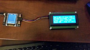
Shortly after I got the SPIDriver, I obtained the similar I2CDriver through CrowdSupply. It’s made by the same folks, and has a very similar interface. The software provided is different though. Anyways… I managed to figure out the ‘C’ programming language interface, added a missing “i2c_stop” prototype to the header file, and get it working in test.
I purchased a TC2004A LCD display from Amazon, here is the datasheet: TC2004A-01 .
The I2C Interface
I2C means Inter-IC-Communication, with the “2” originally meant to be superscripted, as in “I squared C”. It was developed by Phillips Semiconductor in the 1980s. It’s a relatively slow, but pin-efficient interface… not as efficient as Dallas Semiconductor’s “1-wire” interface, but more ubiquitous – available everywhere, and adapted for many uses.
The I2C Display
Anyways, modern LCD displays all seem to have a built-in I2C interface. It’s slow, but it works. More on the speed, and tricks to get around this, later.
I2C Conversion Chip
The old parallel interface appears to still be there, but there’s almost always a daughterboard attached containing a PCF8574 I2C-to-parallel conversion chip. Here’s the datasheet for the conversion chip : PCF8574 .
Display Controller
The original Hitachi HD44780 controller chip is still there, here is datasheet: HD44780 . There appears to be a second source now, the Sitronix ST7066U, here is datasheet: ST7066U_v2.4 .
The HD44780 and friends, always did have a 4/8 bit bus, based on the Motorola MC6800 bus interface – probably because Hitachi second-sourced a bunch of Motorola MC68xx parts in the 1980s. But I digress 🙂
Anyway, this bus had two control lines:
- RW – read/write. This is actually “read/not write” but many source code languages don’t like the embedded use of slashes in symbol names, and it’s difficult to do an above bar in most simple word processors. Anyways, this is high for read and low for write. Its state is latched on the rising edge of E and must be stable through the end of E high.
- E – enable. This is an active-high strobe.
The HD44780 has one address pin called RS for register select. Like RW, this is latched on the rising edge of E and must be stable through the end of E high. When RS is low, the command/status register is accessed. When RS is high, data memory is accessed.
There are eight data lines, D0 through D7. Generally, outgoing data must be valid before the rising edge through the falling edge of E. Most devices latch the data in on the falling edge of E, although this is not always the case.
Connections from I2C Conversion Chip to Display Controller
With only 8 bits total output from the I2C conversion chip, the display only implements the 4 bit interface. The 4 bit interface is made up of only the top 4 data lines, D4 through D7.
|
HD44780 Input |
PCF8574 Output |
|
RS |
P0 |
|
RW |
P1 |
|
E |
P2 |
|
D4 |
P4 |
|
D5 |
P5 |
|
D6 |
P6 |
|
D7 |
P7 |
To control the HD44780, the bus interface has to be emulated by bit-banging. It takes multiple I2C transfers to do a single transaction.
More than Two Lines
The original HD44780 could control one or two line character displays with lines that were up to 64 characters in width. Today, displays often have more than two lines, but generally not nearly as wide as 64 characters – most often, not even half this… so they split the lines.
The original internal display ram was 128 bytes of addressable memory. The top line at addresses 0x00 to 0x00+LINE_LENGTH-1, the lower line at addresses 0x40 to 0x40+LINE_LENGTH-1. The rest of the memory was present and could be used as scratchpad memory, with no effect on the display.
What modern displays appear to do, is split the display into multiple 2-line parts. The top two lines work just like the original, using addresses 0x00 to 0x00+LINE_LENGTH-1, and 0x40 to 0x40+LINE_LENGTH-1, as before. The third line uses addresses 0x00+LINE_LENGTH to 0x00+(2*LINE_LENGTH)-1, the fourth line uses 0x40+LINE_LENGTH to 0x40+(2*LINE_LENGTH)-1.
So, in my case, for a 4 line by 20 character display, the lines start at 0x00, 0x40, 0x14 (decimal 20) and 0x54 (0x80+decimal 20), respectively.
There are also devices that have larger displays – more rows, or longer lines that don’t allow them to play the “split original 2 lines” trick. For this, the common approach is to use two HD44780 controllers (or equivalent), and have 2 “E” signals.
Accessing the Display
As with the SPIDriver, there are an assortment of drivers and sample programs provided to play with. I built the little i2ccl ‘C’ program that was provided, and that showed me the basics of access. I reviewed the lcd1602.py script. That gave me everything I needed. I adapted a very old LCD access library that I wrote many years ago, do use the i2cdriver functions. I wrote a ‘C’ program called TestLcd which exercised these libraries, and found all kinds of errors (of course).
Embrace… CG Characters
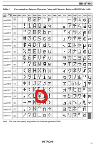
One of the cool features of the HD44780 type displays is their ability to display compose characters, or CG characters. You can compose up to 8 arbitrary different 5×7 patterns, store the patterns in RAM, and access them just like regular characters. This is helpful, because, well, the character set is a little weird – having some kind of foreign symbol where backslash should be, value 0x5C – see below.

It can also be cool for creating industry-specific compose characters too. For instance, my first exposure to the HD44780 was in the late ’80s, where we designed it into the Kodiak Scoretec scoreboard system (I developed the electronics for the remote keyboard assembly, eventually became responsible for support of the entire system). It had little numbers for periods, number of fouls, a little football for possession, special characters for bonus etc.
Extend… CG Palette
The LCD library has the concept of a CG palette. There are far more than 8 compose characters defined, but only 8 can be used at any given time. When this library tries to display a CG character, it checks to see if it’s already in the palette. If it is, it uses it. If it is not, it finds an available CG location, loads it with the desired CG character, and uses it. If there are no CG locations available, it displays a question mark ‘?’.
I added a function to this, so that if no CG locations are available, every present CG character is cross checked to every character in the display RAM, to see if that CG character is presently in use. The first CG location that’s not in use, is removed to make room for the new CG character. At the end, if there just aren’t enough CG locations, again a question mark ‘?’ is displayed.
Extinguish… Backlight and Display Clear
I changed the clear() function to use the direct clear command, instead of writing spaces out to the screen. Much faster!
I also added a function to control the backlight, seeing as it can be turned on and off using I2C.
Speed, Speed… Always Need More Speed!
It turns out that accessing the display through I2C is quite slow. Now, I found a few easy things to speed things up… and there may be places where I can save time, but are more complex. However, those may be for a later time.
I modified the library to check whether a character is already in the display, before writing it out. If it is already there, it skips the write, saving precious I/O time.
Compared to the I/O time, the processor time is nothing, so this speeds things up considerably, especially if very little changes from second to second… like maybe, in an IRIG-B decoder display, hmmmmmm?

