Developed the Kodiak Scoretec Ultimatic U1000 Scoreboard Controller

Initially, Kodiak came to Vansco to fix a problem on their previously-developed MOS 6502-based shot clock.  There was some kind of a bug in the code, and all they had was a paper listing.  They didn’t even have the binary, just a working EPROM!  I found the bug, rolled out the EPROM to disk, patched it in binary with a jump to a previously unused area, and gave them the binary to program future systems.  All in about 24 hours.  They were pretty impressed, so they brought a project to us for the development of their next generation system.

The previous generation was functional enough, but had a huge circuit board with hard-wired digits.  We were tasked with coming up with an easier-to-service, more modular system.

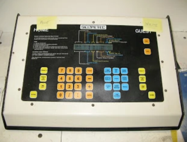
I selected the NEC V25 processor as the core of the design, and an Optrex 24×2 line alphanumeric display.  We used simple Omron B10 switches for buttons, behind a custom screened Lexan overlay – which would be changed for different games.  The software would generally change too, of course.

The large scoreboard panel operated on wall outlet power, of course, which was stepped down for operation of small 12V incandescent lamps.  The panel used an MC68705 processor programmed by Mike Stasenski, decoding a synchronous data stream sent by the keyboard unit.

The key innovation here was that the panel boards could be daisy-chained to arbitrary length, allowing for flexibility in panel design.  Smaller panels could be made less expensive by leaving off the later units in the chain – well, of course, we selected those panels that would be optional to be later in the stream.  Hmm, actually the data came out first in the stream, so that it would shift “off the edge of the world” on units not equipped with the extra digits.

John Janiw was the brilliant mind behind the layout and operation of the keyboard.  He knew so much about all the games, their rules, and how to make the operation intuitive!  Frank Herzog did the programming, actually compiling the code in QNX 2 but targeting for the bare-metal operation of the keyboard’s V25.

Frank and Mike later left the company, and I was the only one on the development team left, so I was supporting this product, both hardware and software, to the end of its life.   The last work that I did on it was in 2006, while Jason and I were operating our consulting company, Elecsys Solutions.

Developed Transformer Winding Controller model 114000

This was the last in the series of transformer winding controllers developed for Micro Tool and Machine.  It was an amazing work of their craftsmen!

The main mandrel was driven by a large stepper motor, giving fine pitched accuracy on the winding.  There was a second, smaller stepper motor driving a traverse that payed out the wire onto the mandrel,  moving left to right on a lead screw.

The mandrel and traverse stepper motors made characteristic sounds as they indexed, accelerated and decelerated, giving the machine a unique personality.

There was a tap forming head above the mandrel which moved with the traverse head, through which the wire passed.  At a given point, the mandrel would stop, clamps would come down onto the wire on either side of the tap former, a clamp wrapped the wire in the middle, then twisted 2 complete turns as it pulled up – while the clamps on either side, operated with pneumatics, would slide in.  This formed a perfect wire tap, where a long bolt could be passed through to the top of the transformer.

The placement of the wire tap was critical, otherwise the tap bolt would not line up with the insulator and hole in the casing.  I took very careful measurements of all aspects of the machine, then worked the math so that I could determine exactly how far ahead to stop the mandrel to make the tap, and then have it wind down to the correct spot.  As the rotation speed of the mandrel was well known (and set by the controller using a stepper motor), a payout encoder on the wire at the tap former gave constant information for the circumference of the winding.  From this, and knowing the geometry of the machine, the exact point that the mandrel had to decelerate and stop, could be calculated.   The amazing thing was – it worked!

The last cool feature of this machine was duct tap insertion – a compartment of insulating rods was kept on the side, and could be pneumatically pushed up into one-way catch slots on the ends of the winding mandrel.  This provided spacing between layers, or between windings.

All of this made for a fantastic sight.  Almost autonomous transformer winding!  Although the operator was still required to baby-sit the machine, in case anything went wrong.  Of course, they had to change wires for LV and HV (LV wire was more like a wide copper foil), weld to the ends (propane welding of copper!) and tie off things when appropriate.

I was so enthused about it, that I borrowed Lorne’s camera and made a video of it in operation.  I’ll have to dig up that tape, digitize it and post it sometime!

The machine had multiple processors on multiple boards, coordinating all this activity.   The traverse controller was implemented with a Motorola MC68701, programmed by Lorne and by me; the tap forming controller was implemented with a Motorola MC68705U5, programmed by Mike Stasenski, and I did the programming on the MC6800 on the main controller, coordinating all their activities.  I designed the “piggyback board” which contained the very-cool PCL-240K stepper motor controller for the mandrel, the “traverse board” and the “connector board” where all the different boards wired to for the interchange of communications.

This machine went to Delta Transformers in St. Jean-sur-Richelieu, Quebec.  In 1988, I visited the plant and saw my machine in action.  The engineer responsible for the machine, Guy Desormeaux, told me that the company had recently been acquired, and that this transformer winding machine was fiercely sought after!

Developed Transformer Winding Controller model 109000

This was one of a series of transformer winding controllers developed for Micro Tool and Machine.  It used an variable speed eddy current clutch with induction machine drive.  As part of a three-person development team, my responsibility was for the electronics, and for the main controller software development.  Like the CMP3000 and other Micro Tool systems, the main controller of the model 109000 was a Motorola MC6800.