Filipe and I have been looking into expanding and extending the Eye on the Ice(tm) system for Hans Wuthrich of Ice Consultants International. The original system was developed around 2008/2009 by my team at Norscan Instruments Ltd., back when we were diversifying our product offering. I was Product Development Manager with a fantastic group of very talented people working with me. They did a great job of the design of the Remote Measurement Module (RMM), the Collector Module (CM), and the MS-Windows software that went with it. It’s a great system!
Alas, RF modules eventually go obsolete, and the ones used in the Eye on the Ice system will likely soon be unavailable. They might be around for a few years, who knows, but the writing is on the wall – technology changes, RF emissions regulations tighten, and products change.
Last fall, and into the new year, Filipe and I did a proof-of-concept for an in-ice Eye on the Ice sensor which would use Silicon Labs Zen Gecko EFR32ZG14, the Zen Gecko. Although the system did work, we found that the low-level control of a mostly-asleep sensor was going to be a huge job. The examples given, and the information provided, just weren’t enough to get us over the challenge. In addition, the Z-Wave devices appear to “retry themselves to death” if the central station goes away – not a good thing for a low-cost, sealed temperature sensor device.
One thing that looks like an interesting alternative is the LoRa system – long range, low data rate, adaptable for different jurisdictions. Probably an excellent alternative for transmission of data like Eye on the Ice.
The Reyax web site has a few interesting LoRa modules. Their modules use “AT commands” to set centre frequency, spectral parameters, and data rate. With that in mind, these modules could almost be a drop-in replacement for the present Linx FHSS modules that Eye on the Ice uses!
Then I found the Hope RF series of LoRa modules, very interesting, especially the RFM95W. It looks like it’s just what we need. It does simpler modulation as well, just by flipping a bit in its configuration. You would lose all the error correction hyper sensitivity, and built-in spread spectrum, but it would be an easy way to establish simple communication. There seems to be plenty of documentation on the chip, the RF95. If you Google “HopeRF RF95”, you will find RFM95_96_97_98W.pdf on the SparkFun web page, which gives comprehensive documentation of the chip, its operation, and its registers. I suspect SparkFun stocks, them, and Digi-Key has them as well. There appears to be a nice Demonstration Kit, the RFDK_RFM95, but I can’t seem to find a vendor… GorillaBulderz in Australia lists them but has no inventory, and no indication of when it will be in stock.
I’ve been playing, on and off, with IRIG-B decoding – first, modifying NTP source code to continuously dump decoded data from what it reads on the audio input port… then extracting the IRIG-B decoding code to a stand-alone program which would read from the audio input port and output decoded data… then added unmodulated IRIG-B decoding (which was a challenge, due to audio bandpass limitations, but I made it work)… then putting it to an LCD display, then another, then another with keypad…
Through it all, I struggled to find a practical way of making it useful. After a discussion with Norbert of ERLPhase, I think maybe we came up with something.
Mobile Device Use?
Rather than expect someone to load up LINUX onto their laptop, drag the laptop to the site where the IRIG-B source is, and use a special cable to connect to the audio input port… why not use the mobile device that everyones seems to carry around with them?
I briefly tried to capture the IRIG-B signal (modulated and unmodulated) into a mobile device, without success 🙁 I tried both my Samsung Galaxy S5 (SM-G900T) and my Samsung Galaxy Tab S2. No luck. Maybe my physical setup might have been a bit precarious – I found out later that my audio jack connection may have been suspect – but, the result, even when it did seem to get signal, was not good. A severely attenuated low frequency response (basically gone below about 100 Hz) made it almost impossible to decode the audio captured by either device.
Create a USB OTG Device?
Having used the Silicon Labs‘ Universal Bee EFM8UB2 processor last year while working at ERLPhase, and after talking to Norbert… why not capture the IRIG-B signal on the USB2’s analog input port, and then funnel it to any customer’s mobile device through the UB2’s well-integrated USB port? After all, most modern Android devices support USB-on-the-go, where the mobile device can act like a USB host (similar to a computer) or a USB device (similar to a USB flash drive, camera, or MP3 player).
I thought maybe the EFM8 could do simple 8 ksamples/second signal acquisition (the sample rate used by NTP and later read_irig programs), then send packets of data to the mobile device, where it would be saved to a file that would be submitted for post-acquisition analysis. This way, the burden of processing would be moved from real-time to remote post-acquisition, maximizing the likelihood of successful data capture.
The SLKSTK has a neat little graphical LCD display and a few buttons on it, and one example supplied was a simple oscilloscope program EFM8UB2_Oscilloscope which could acquire data on an analog input at 24 to 500 ksamples/second. I created a custom version of this software locked at a sample rate of 8 ksamples/second with favourable amplitude and trigger settings. I was readily able to see unmodulated IRIG-B waveforms! Unfortunately, the EFM8 device only does unipolar conversions, and SLKSTK doesn’t have any circuitry to enable bipolar input – so modulated IRIG-B would only show half cycles.
I introduced a crude offset by wiring a 47k bias resistor to the analog input from the 3.3V supply bus. Together with the 10k-22k-10k divider chain on the input, this gave a reasonable DC offset, so both modulated and unmodulated IRIG-B could be seen.
VCPXpress Echo
A second example supplied was a program to emulate a Silicon Labs CP210x serial port on the USB interface, EFM8UB2_VCPXpress_Echo, which performed a simple reflection echo of characters sent out.
To prove that it was working, and not just a local echo from minicom – ugh sometimes minicom frustrates me – I modified the Echo program to echo every character twice, then follow every character with an arbitrary string “Burp!” and carriage return. It took a bit of doing, but it worked.
Oscilloscope with added VCPXpress USB Transmission – Failed
Well, I had the 8 kS/S data acquisition in my modified Oscilloscope project, so I mashed it together with the VCPXpress libraries… and got crap. It seems as thought the whole thing messed up the link process so badly that symbols resolved, but overlapping memory areas caused unpredictable behaviour… and it would not run. There was just too much gratuitous complexity in the Oscilloscope project. So, I thought I would work the problem from the other end.
Starting with VCPXpress
I started with EFM8UB2_VCPXpress_Echo, putting out canned strings. I wrote a simple Python script on my LINUX machine to accept the strings. That worked.
I added framing and a packet structure to the strings, and decoding into the Python script. That worked too.
I had thought that I’d send the full 10 bit ADC values, packing them as needed into the serial stream. However, the nominal line rate is 115 kbaud, or about 11,500 characters per second. Sending 8 kS/S of 10 bit data would take 10,000 bytes per second. With 5 bytes of overhead per packet, and 50 bytes of data per packet, then this 10% overhead would result in 11,000 bytes per second, not enough margin to make me feel comfortable that it would be a robust transfer.
In fact, I decided to add 2 more bytes of overhead per packet – a running binary sample count, to tell if overflow or underflow had occurred – so the overhead is now 14%.
Now, the original NTP code only used 8 bit samples, and seemed to work just fine. So, why not reduce the data size to 8 bits per sample? Then 8 kS/S of data would be 8,000 bytes per second, and with 14% overhead, still “only” 9,120 bytes per second.
It turns out that the 115 kbaud line rate is conservative, and really only even supported to make legacy software happy – the USB connection is far faster than this, and will transfer much more data than the stated. So, in the end, with 8 bits per sample, the link is very solid.
Here’s the packet format:
00 --------- SOH
01 --------- TYPE - Echo of Command (presently fixed)
02 --------- DATLEN - Data Length (binary)
03 -------+
 .        +- DATLEN bytes of binary data
 .        |
DATLEN+2 -+
DATLEN+3 --- CKSUM - sum TYPE to CKSUM (inclusive) is zero
DATLEN+4 --- EM - end marker - end of frame
The binary data that I typically send is 52 bytes total, including 50 bytes of analog data:
00 --------- Acquisition Count High Byte
01 --------- Acquisition Count Low  Byte
02 --------- First Data Sample
 .
 .
DATLEN-1 --- DATLEN-2th Data Sample
Data Acquisition and Transmission
I added data code to make the 8 kS/S ADC acquisition, directly timer driven for jitter reduction, interrupt at the end for buffer stuffing. The data was reduced from 10 bits to 8 bits at interrupt level. Two swing buffers were employed, with main line code creating the packet and firing it off to the VCPXpress code for transmission.
Python Processing
Data Reception and Processing
I modified the Python script to receive the analog samples and stuff them into a list, keeping track of whether packets were valid and all samples were present, then writing them to a CSV for processing in a spreadsheet. I was able to verify that the data was transferred intact and complete, with reasonable fidelity.
I then proceeded to decode the unmodulated IRIG-B signal bits as (0/1/Position Indicator/Invalid), and add them to the CSV file output. Then, I decoded the signal bits and compose a string of characters to represent each one-second frame of IRIG-B data. Lastly, if the frame met proper format criteria (PIs in the right places, 1/0s in the right places, not too many bits), I pulled the data out and performed full decoding just as I had done with read_irig in the past. I also added this to the CSV file output.
I actually created three CSV file outputs:
Raw data sample file – with extended columns for bit decode internal data
Bit decode sample file – each bit as it was decoded – with extended column for full decode output when successfully performed
Full decode file – a bit string for each one-second frame, plus fully decoded data
Threshold Detection
It was difficult to consistently get good thresholds for decoding, so I added rescaling. The maximum and minimum values of signal in the file are calculated. An offset is subtracted to centre the signal around zero, then a gain is multiplied to make the signal approximately -3 dB of full scale, or about +/-25,000 counts.
Modulated IRIG-B Processing
It was difficult to decide how to work with modulated IRIG-B. The original NTP code did a kind of phase-locked loop decode on the signal, so it could recover the bit stream, but also the precise zero cross time, so the local clock could be time sync’d to the IRIG-B signal. I didn’t want to do this. The code is hard to understand, we don’t need time sync for post processing, and I’d rather not incorporate someone else’s code if I don’t have to.
Instead, I went back to the way that Filipe and I designed modulated IRIG-B processing so many years ago: watching for positive side pulses due to the sinusoid going above zero (Polarity), and also for “high” level amplitude by positive side pulses due to the sinusoid going above a threshold (Peaks). Polarity without Peak means low level cycle, Polarity with Peak means high level cycle.
One problem was an unknown baseline. As mentioned, an arbitrary offset had been applied. The maximum and minimum values of signal in the file are calculated. Zero cross was assumed to be at the halfway point – the median – the average of maximum and minimum – this gives Polarity.
The amplitude of a low level cycle is defined as 1/3 the amplitude of a high level cycle. The threshold would be halfway between these two levels, or 2/3 the amplitude of a high level cycle, or 5/6 of the way to maximum level –
minimum + (5/6 x (maximum – minimum))
Now, I tracked how many high level cycles in a row happened before low level cycles resumed. This would determine whether a bit was a 0/1/Position Indicator.
Tarball and Steganography
I added a feature to roll the three CSV files up into a GZIPped tarball. Because the files are ASCII, they compress well. Then the original CSV files are deleted. A tarball is easier to transfer for post processing.
A tarball might not pass E-mail inspection, so I added a steganography library to encode the tarball into an arbitrary JPEG image. The JPEG image would likely get through the E-mail system more easily. However, this processing took a very long time (over 10 minutes) and created a huge image file (original 100k, over 5 Meg afterwards), so this was abandoned.
Improvements
Automatic Gain Control
By putting the EFM8 MCU’s VREF on an RC-integrated PWM output, and using the same signal as a DC bias offset on the analog input, I could change the bias and the ADC span under program control.
I added code to the EFM8 to track the maximum and minimum ADC input levels (single ended) and calculate whether the system gain should be increased or decreased to make the span approximately 128 counts, or about half scale. Margin is maintained, but gain is maximized. The system is designed to track within a second or two of amplitude change.
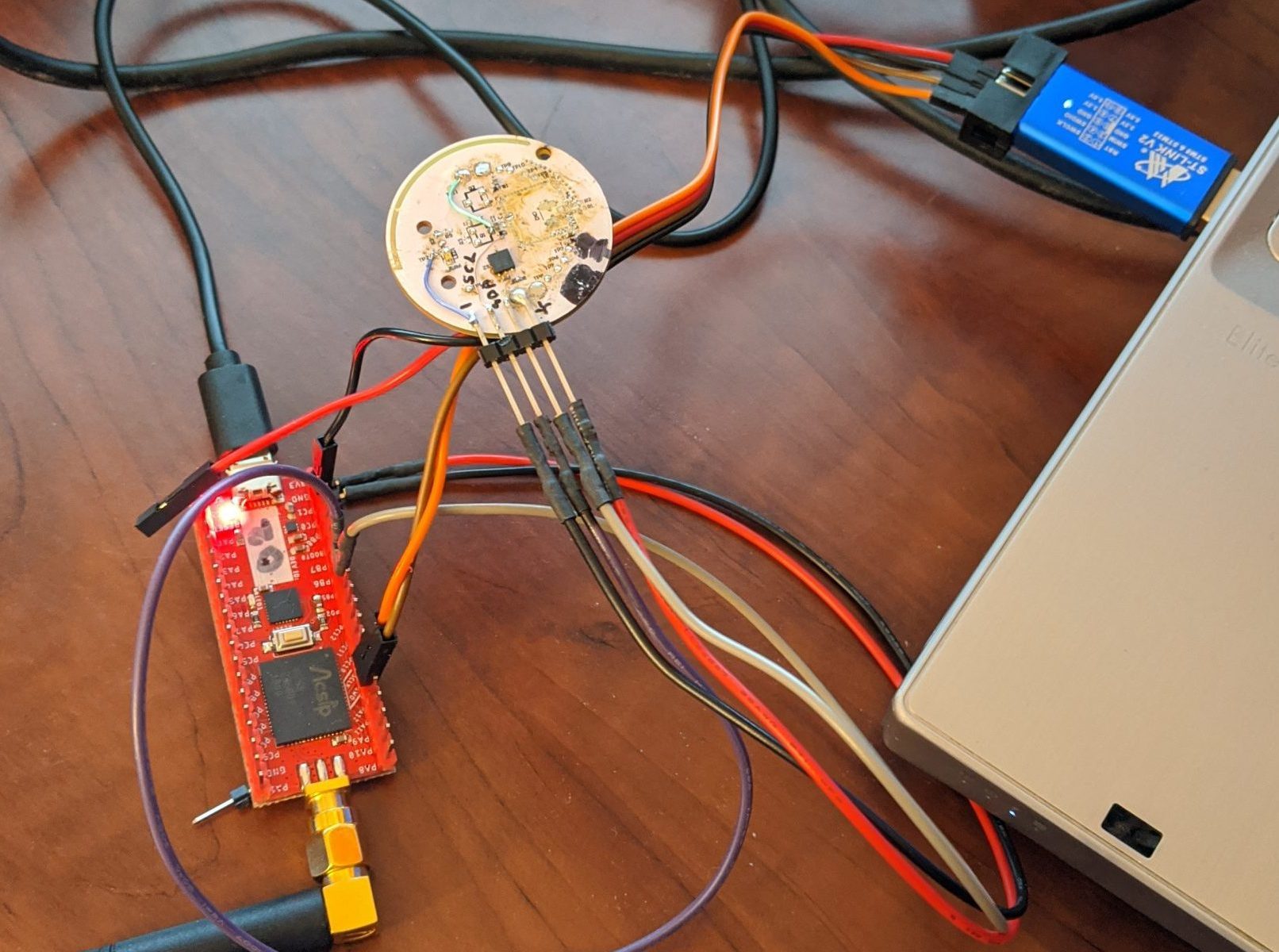
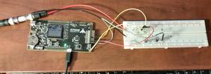
Building it Onto a Beadboard
The analog circuitry was put onto a breadboard and wired to the EFM8 MCU on the development kit.
Silicon Labs SLKSTK2001A EFM8 UB2 Universal Bee Development Kit with Simple Analog Front End
Next Up
Next, to connect this to a mobile device, invoke a serial port driver, and capture the data there for post processing analysis. That’s easier said than done!
My dad passed away a couple of years ago, in February 2017. We were estranged. It’s a sad tale, I suspect too often repeated in many families. Fights, misunderstandings, dumb egos, idiotic attitudes towards children and parents, and other assorted foolishness.
Dad had moved to the Philippines around 2013, but I didn’t know that until some time later when a woman tried to contact me, claiming to be his new (but already estranged) wife there. I declined to get involved in their child custody fight – I know nothing of the situation, knew nothing of his whereabouts or his activities, and only had her word on it all.
I am kind of sorry that I didn’t at least try to track him down, not to assist her, but to at least make contact, while he was still alive. Sigh.
Apparently, a heart attack felled him, at the age of 77. That’s not all that surprising, as he smoked on and off throughout his life – most of the time I knew him, he was puffing away. One of the reasons why I can say that I will never smoke. Haven’t had a single one yet, and don’t intend to start – and I hate the smell. Well, enough about that 🙂
Running off to join… the Railroad?
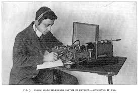
But, 60-some-odd years prior, he was a strapping young lad of, oh, probably 17 years of age (1957?), when he quit school and went to work for the CNR station in his hometown of Makinak, Manitoba. He signed on as a telegrapher, then moving all around Manitoba and Northwest Ontario, working out of one horse towns, sidings, and places-in-the-middle-of-nowhere. I know that he worked a time in Churchill, around the time I was born – because my mom says that they would do “check-in” calls once a week – he would make a person-to-person call asking for himself – which my mom would of course decline, saving the toll charges, but knowing that he was still alive. Long distance charges were pretty steep in those days, and money was tight for my parents.
My dad left the railroad sometime in 1963 or 1964, apparently when the switch from telegraphy to teletype was on. The railroad left a lasting impression on him, though – he had a lifelong love of trains, talked fondly of his time with the railroad, and cherished his telegraphic memories, so to speak. He also used to say that he worked there long enough to get coal cinders in his hair.
When my dad first started, he was shunted around at the whim of the company, working many small places, as mentioned. As he got more seniority, he could stay closer to home. He never did build up much seniority, but he did manage to get work from time to time in “WI Office“, which was the CNR telegraphy office in Union Station on Main Street in downtown Winnipeg.
Experienced Professionals vs the Unskilled
My dad told me that often young men from remote places would learn to use the telegraph, and get work with one of the railways, as a ticket out of the sticks, as they would call such way-off places. Their telegraphy skills would be poor (perhaps like his when he first started out? Hmmm), so sometimes an urban operator in WI office would ask the remote unskilled operator to please send with the other foot, obviously an insult, since operators always sent with their working hand.
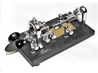
The Vibroplex “Bug” as Telegraph Key of Choice
The Vibroplex “bug” was the high-speed telegraph key that most professional telegraphers used to send code. When you pressed the paddle one way, it closed a solid contact to send “dashes”, but when you pushed the paddle the other way, a weight and a spring caused a second, smaller contact to bounce rhythmically to send “dots”. The weight and spring can be adjusted to change the speed of the “dots”.
Dad was a southpaw, a left-hander, so he a rather special version of the Vibroplex “bug”, the relatively rare left-handed bug. I still have that key, somewhere, in its original box. It’s dusty, but it still works well.
A Vibroplex left handed Bug
WI Office Telegraph Traffic
My dad told stories a row of operators working in WI Office, with the telegraph sounder on a swing arm moved up close to your ear, so you could hear your own signal over the din of the all the others. You would listen to the Morse code and type on an old manual Underwood wide carriage typewriter. I had one of those typewriters for many years. Oh, but the code used was American / Railroad Morse, not International Morse.
Often the traffic received was mundane in nature – freight car contents and their movements, inventories, and manifests. Sometimes commercial traffic was exchanged – so called “sending a telegram”, but mostly it consisted of information of interest to the railroad.
When doing manifests and forms, the old Underwood would be set up with “hard” tab stops set for the locations of the form fields. I’m sure the old typewriter would be very noisy too, with a “clack-clack-bang, clack-clack-bang, ding-return!”
When shorter forms or messages were completed, they were clipped into a rail above the operator’s station, and whipped down the line to where someone else picked them up and distributed them where they needed to go. Meanwhile, the operator would have already loaded up a new page into their typewriter, probably already partway into copying the rest of the message.
In fact, often operators would not even be thinking as they typed. It became automatic. They typed what they heard.
A Lion Runs Away to Join the Railroad Too?
Now, I don’t know if it was my dad or someone else who had this happen to them, but my dad often told the story of an operator, late at night, who was taking a mundane message. He typed it up, pulled it out of the typewriter, clipped it into the rail, but just as he was about to sling it down the line, he saw the message he had just typed. It said:
FOUND A LION UNDER STATION IN POOR CONDITION.
Wow, that was interesting! Where the Hell did the lion come from?
Dad said that it happened due to an anomaly in Railroad Morse code. Railroad Morse had dots, normal dashes, long dashes, inter-dot/dash spaces, inter-character spaces and inter-word spaces, with supposedly fixed ratios between the lengths of each. A poor operator could change a “T” to a “-L”.
So what happened is someone was sending with the wrong foot, and was trying to say:
FOUNDATION UNDER STATION IN POOR CONDITION.
A simple status report, when messed up, caused some mirth in WI Office!
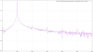
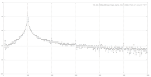
I stumbled across this article a few weeks ago, and kept it open in my browser until I could come up with something (semi-) useful to do with it: Plotting data in the terminal with gnuplot…
I had done some work last year at ERLPhase to analyze some data, including doing FFTs, etc. I played around and did a comparison between JPEG graphics and text graphs. Check it out!
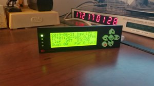
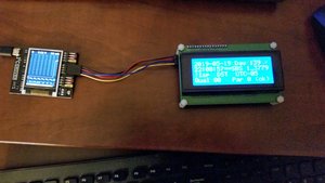
I purchased a Crystalfontz CFA635-YYK-KU 4 line LCD display with integrated USB interface, 4 bicolour LEDs and 6 button keypad, then proceeded to modify the read_irig program to talk to it.
Integrated Display with LEDs and Keypad showing IRIG-B
I’ve modified the keyboard interface a bit as well. Keys now supported:
a - Change backlight intensity (CFA635 only)
d / keypad "DOWN" - Change display format: DECODED, RAW, TITLED
h / keypad "CHECKMARK" - Hold/unhold display
u / keypad "UP" - Reverse RAW or TITLED display order MSbit <>LSbit
r / keypad "RIGHT" - Shift display data right
l / keypad "LEFT" - Shift display data left
v - Diagnostic dump of display data to terminal
f - Change format of terminal displayed data: RAW+DECODED, DECODED only, RAW only
q / keypad "X CANCEL" twice consecutively - Exit program
I’ve also made the top LED blink green bright and dim, each time it gets a time update, solid red when IRIG input fails and a timeout is declared, and blink orange bright and dim slowly, when display is in hold mode.
Of course, using Facebook Messenger on the computer is just as easy as on your phone… or is your phone just as easy as computer? No matter, it’s easy. For other messengers, you have to get more creative.
WhatsApp
This one isn’t too difficult. Go to the WhatsApp web site, then try to log in. It will give you a QR code. Go to your cell phone, get onto WhatsApp, go to the upper right menu, choose “WhatsApp Web” and point it to the QR code… Boom! You have your WhatsApp on your computer and on your phone.
You can’t have WhatsApp web on two computers at once. If you sign on at work (say), then your home computer is logged out. Not too bad though, since it’s easy to sign back in again.
This only works when the phone is on-line and has data through WiFi or its own data connection.
Google HangOuts
This is even easier. If you are logged onto your Google account in your browser, just go to the Hangouts page, and there it is. You can be logged in on as many computers as you want for this.
Hangouts works whether or not the phone is on, or connected.
SMS (Text Messaging)
There are two approaches here. Both requires the phone to be on-line and have data (WiFi or its own data) and SMS access.
Google Messages
If you are on Android or otherwise have access to the Google Messages application on your phone, make that your SMS program. Then you can go to the Google Messages web page and see all the conversations. The nice thing with Google Messages is that, when you read a message on your computer, it’s marked as read on your phone, so the notification goes away.
PushBullet
This is really cool, and was my go-to solution before I had Google Messages. Put the PushBullet application on your phone, then go to the PushBullet web page and sign in on both. You can send and receive your phone’s text messages.
There are two drawbacks to PushBullet. One is that it costs money to sign up and keep it running (sorry, I forget how much). The other is that, reading a text message on PushBullet does not mark it as read on your phone, so the notification stays up until you do read it on your phone (or at least cancel the notification).
Kik Messenger
I think here, you are out of luck. For security reasons, you don’t want to use other company’s programs to dig into the Kik Messenger messages.
I find it cool that I still have the same telephone number that I had in high school. Yes, if you knew what my phone number was in high school, you can still reach me there now.
Once upon a Land Line
My family moved to Headingley, just west of Winnipeg, in October 1971. At that time, Headingley was an independent rural municipality, separate from the city of Winnipeg. We got a rural telephone number (204)-864-xxxx, typical of St. Francois Xavier and Lido Plage, to the west and north, further out of town. This meant that calling into Winnipeg was long distance, even though it was only about 9 km (5.5 miles) away! Very annoying.
There was quite a fuss going on in Headingley at the time. Manitoba Telephone System (MTS), the government owned monopoly on phone service, claimed that if we wanted to have local calls to Winnipeg, then we had to be part of the city. That was crap. Communities to the northeast of the city, like Lockport, had local calling to the city, and were not part of the city. The city of Winnipeg was actually several independent cities at that time, each with its own council and mayor/reeve.
Nonetheless, around 1972 the province of Manitoba amalgamated all the independent cities in an effort called “Unicity”, and in so doing, subsumed Headingley into the City of Winnipeg. Now, I think that the Unicity concept was a good thing, especially in the area of control of development – although on the other hand, Winnipeg hasn’t done a very good job of development control… more on that, another time.
So, around 1972, my family got a new Winnipeg phone number, (204)-xxx-1334. All of my friends knew this number, of course. And I knew all my friends’ numbers. It was what we did in those days!
Dean gets his Own Phone – in His Basement Lab
Around 1980 or so, while living at home, I was frustrated by not being able to use the phone when I wanted to, and I had decent income, so I got my own phone installed into my lab in the basement, (204)-xxx-5620. I was so thrilled! When I tried to call my best friend Dave, his number was disconnected… oh no! It turns out that when I was at Polo Park getting my number assigned, Dave’s mom was at another MTS store getting a new number as well, and she got the one just before mine, (204)-xxx-5619. My personal number is long gone now, but she still has hers, and that’s how I remember it – one less than mine, ha ha ha.
Grabs Control of Old Family Telephone Number
Later, when Dayna and I bought the house and moved out to Headingley with Eric, I called MTS and told them that they had my first initial wrong (my mom’s initial is “M”), so effectively transferred the phone to me, heh heh. Later, we “ported” the number to Shaw, our cable TV and Internet provider.
When I moved away in 2011/2012, Dayna let the phone lapse. I called Shaw to get my own phone, they told me it had lapsed, so I picked it up again.
Moving to VoIP… and to Arizona!
In 2013, when I moved to Phoenix, I ported it to VoIP provider Les.net. I had a Grandstream HandyTone 286 adapter, with a 4-phone Uniden cordless telephone system. It was very nice in Phoenix, as I could have several phones about the house.
Way cool, I had my long time Manitoba telephone number, and it rang in Phoenix. Caused pollsters and telephone solicitors no end of confusion, hehehe.
Adding Numbers
While I was in Phoenix, I actually signed up for a couple of other Les.net numbers, including a conference call number in Winnipeg, conference call number in Phoenix, a toll-free (800) number, just going crazy 🙂
Toll Free Line
The toll free number was to encourage my mom, my son and my brother to call more often, if they had no long distance.
Conference Call
I used the conference call number for governing board teleconference meetings, when I was chair of SAE Arizona & Nevada Section. It was a bit expensive, as it cost me 1.5 cents per minute per caller… and, as I seem to recall, it cost me big one time that someone didn’t hang up before I did!
Features
All the telephone numbers rang to the same phone. It worked well. An additional feature was an embedded answering machine – a message left on any number would be converted to a WAV file and E-mailed to me. I could get them anywhere, how convenient.
And the cost was low, low low! It’s about 3 a month for an account, which includes an automatically assigned Winnipeg number, then about3.50 a month to maintain the 1334 number that I ported from Shaw. Calls were about 1.5 cents a minute (one way more expensive than the other, don’t recall which), so it was really difficult to get up to $10 a month. Nice!
Now, the sound on that system was not great. The big challenge that I found was that there appeared to be a significant transit delay for the data. It’s amazing how very small delays, say 100 mSec, can be extremely frustrating. You think someone else is stomping on you during talking, but it turns out that it’s because of the small delay. You have to keep that in mind.
Mom’s “Long Distance Phone”
It worked well enough that I got my mom a Grandstream HandyTone 486 and a 2-phone cordless telephone system, intended only for making calls. She saved a lot of money using it to make all her long distance calls.
Moving back to the ‘Peg
When I moved back to Winnipeg, I ported my Phoenix cell phone (480)-xxx-5952 into Les.net as well, so I could continue to receive calls and exchange texts with folks who had that number.
Porting to VoIP.ms and Getting a VoIP Desk Phone
One day, I found out about another VoIP provider, VoIP.ms. I started an account there, just to see how well it worked. They had better sound quality, and more services, so I transferred my (204)-xxx-1334 and (480)-xxx-5952 to Voip.ms and got a Grandstream GXP1620 2-line VoIP desk phone. I love it! The sound is awesome, practically perfect, way better than my cell phone. I have one line on each number. Even better, the (204) number costs 1.70 a month, and the (480) number costs0.85 a month. I’m paying about 1/2 cent per minute on the (204) number and about 1 cent per minute on the (480) number.
Headset Highly Recommended
When I started applying for jobs all over the place, and having to do so many telephone interviews, I got a DailyHeadset model 4332802404 (ASIN B076KP2SX4) on Amazon (where else 🙂 ) which plugged right into the GXP1620 and worked flawlessly. It is fantastic.
SMS Almost as well as a Real Cell Phone!
VoIP.ms actually has an Android application that can text (SMS) through an SMS-enabled account, and my former Phoenix cell phone number (480)-xxx-5952 was such an account, so I can text message anyone in the USA almost as easily as before. The only thing is that it doesn’t support MMS (pictures, songs, and videos), so, don’t even try. On the other hand, you can do SMS from VoIP.ms’s web-based portal, so you can SMS from your computer.
They also have the “VoIP.ms SMS” Android application that can use your mobile phone’s data plan to do SMS almost as well as native SMS. Follow the directions on the VoIP.ms website, you have to set up a “callback”.
The Android application can host SMS for multiple telephone numbers at the same time, allowing you to select between them.
A recent update: it appears that they’ve made SMS available on my original land-line phone as well, so perhaps they’ve lifted the requirement that it was originally a cell phone, to make SMS texting work.
Send and Receive FAXes Too!
VoIP.ms also has FAX numbers you can rent for $2 a month. That lets you send and receive FAXes using E-mail to/from your computer! It works great. I’ve used it only a few times, but it’s a neat toy nonetheless.
Caller ID Foibles
The one challenge that I’ve had using VoIP.ms is the caller ID information on outgoing calls.
I don’t know if it’s my VoIP desk phone or the VoIP.ms system, but it sometimes gives the Arizona number for calls made from line 1 (the Manitoba line) and the Manitoba number for calls made from line 2 (the Arizona line).
Eric also reported that his phone claimed I was calling from Egypt (country code +20), so his phone was misinterpreting the caller ID information. The start of the “204” Manitoba area code was getting interpreted as the country code. Contrary to what VoIP.ms tells you, when it asks you to give the 10 digit caller ID number, give them 11 digits, prepending the “1”, and that fixed the problem.
Incoming Calls: the One Challenge
For some reason, incoming calls have been a challenge. The VoIP server must be able to route back to your VoIP phone, in order to ring it and set up the connection. Years ago, this seemed easy, and it all worked. Of course, I didn’t make any notes about how to set it up (argh). But recently, I found out that neither of my numbers would ring through to my desk phone. Curses.
My solution was to forward a bunch of ports through my firewall to my VoIP phone. UDP ports 5060 (1st line), 5062 (2nd line), and 10000-10200, to be precise. Then I had to deal with my dynamic IP resolution. Well, I have a subscription to dyndns.org, so I can readily resolve (say) something.dyndns.org (or whatever, they have lots of options for TLDs) to my local firewall’s outside address. The challenge is getting the dyndns.org (oops, now that it’s owned by Oracle, they call it dyn.com) server updated. In the old days, I used an old WRT-54G firewall/router flashed with DD-WRT. That worked well back in the day, but I’ve abandoned it recently because the WRT-54G got a bit sluggish and lacked features (like 5 GHz band support). If you go that route, be careful – there are a lot of WRT-54G variants, and not all of them can be flashed to DD-WRT… and some that can, are restricted in functionality once flashed.
Anyway, without my handy DD-WRT router, I set up a Raspberry Pi that runs inside my network, with ddclient connected to dyndns (see directions), which keeps the IP address on dyndns pointed to my firewall/router.
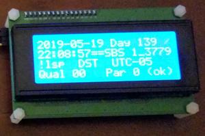
Well, I did it – what I’ve been trying to accomplish for some time now. I have a “live” decode of IRIG-B to my little 5×7-character-based LCD display.
Pulling Threads
I created two new threads in my read_irig program.
One thread reads the keyboard, looking for single character commands:
q: quit read_irig
d: show decoded data
r: show raw data 3 lines at a time (60 bits at a time), and if raw data already showing, reverse the bit sequence
t: show raw data 1 line at a time (20 bits at a time) with header, and if already showing, reverse the bit sequence
u/l: move between windows of present format up/down (e.g. show next or previous 20 bits of raw data)
h: freeze the display at the present time
The second thread takes a full structure of present time data and displays it on the screen, in accordance with the present format and situation.
Displayed Output
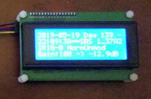
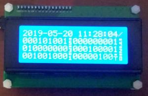
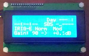
Decoded Display
Decoded Time Display, showing decoded date, day of year, time of day (HH:MM:SS and straight binary seconds in hex)Decoded Data Second Page, showing format, gain and amplitude of signal
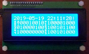
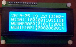
Raw Display
Raw Data, showing chips 0 to 59Raw Data Second Page, showing chips 40 to 99
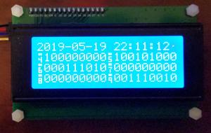
Reversed Raw Display
Reversed raw display is convenient because the bits are arranged from most significant (MSB) to least significant (LSB) from left to right, which is convenient for most people to read.
Reversed Raw Data, showing chips 99 to 40Reversed Raw Data Second Page, showing chips 59 to 0
Timeout/Searching for Signal Display
Timeout Indication, showing blanked out data, presently searched-for signal type, gain and amplitude of signal
What’s Next?
I was thinking that I might introduce a third display mode, that of raw data with headers, more like the console output of read_irig:
#
#--------------------------------------------------------------------------------------------------||------------------------------------------------------------|
#           Normal Unmodulated IRIG-B Raw  (noninv audio)  (Gain  93 giving  +1.0 dB)              ||   Normal Unmodulated IRIG-B (noninv, gain  93 ->  +1.0 dB) |
# StrtBinSecs (SBS) |    Control Bits   |   Year  |    Day of Year    |  Hours  | Minutes |Seconds ||Day|   Date and Time    |SBS hex|Leap| DST |Offset|Qual|Par |
# ........ .........|......... .........|.... ....|       .. .... ....|  .. ....| ... ....|........||...|.... .. .. .. .. .. | . ....|....|.....|......|  ..|....|
#                   |                   |         |                   |         |         |        ||   |                    |       |    |     |      |    |    |
.001010101.010111101.000100000.010111000.000101001.000000001.010000000.000100010.000001000.01001001. 140 2019-05-20 12:08:29   0_AABD !lsp  DST  UTC-05   00 1 ok
.001010101.010111110.000000000.010111000.000101001.000000001.010000000.000100010.000001000.01100000. 140 2019-05-20 12:08:30   0_AABE !lsp  DST  UTC-05   00 0 ok
And Then, and Then!?!
You think that would be enough for me? Well, apparently not! read_irig takes very little computing power, so it could easily run on a smaller processor… say, an ARM… on a Raspberry Pi, or a Beagleboard – then it could be made portable. I have two Beagleboard Blacks and like them. The problem here is that none of these boards have easy audio input ports, like my laptop. Some do have ADC inputs, but they need to be protected, amplified, provided with a jack, etc. Hmm, have to think about this.
Almost every device these days has an I2C port, so there shouldn’t be much trouble there.
I2CDriver with TC2004A 4 line x 20 character I2C based LCD display
Shortly after I got the SPIDriver, I obtained the similar I2CDriver through CrowdSupply. It’s made by the same folks, and has a very similar interface. The software provided is different though. Anyways… I managed to figure out the ‘C’ programming language interface, added a missing “i2c_stop” prototype to the header file, and get it working in test.
Anyways, modern LCD displays all seem to have a built-in I2C interface. It’s slow, but it works. More on the speed, and tricks to get around this, later.
I2C Conversion Chip
The old parallel interface appears to still be there, but there’s almost always a daughterboard attached containing a PCF8574 I2C-to-parallel conversion chip. Here’s the datasheet for the conversion chip : PCF8574 .
Display Controller
The original Hitachi HD44780 controller chip is still there, here is datasheet: HD44780 . There appears to be a second source now, the Sitronix ST7066U, here is datasheet: ST7066U_v2.4 .
The HD44780 and friends, always did have a 4/8 bit bus, based on the Motorola MC6800 bus interface – probably because Hitachi second-sourced a bunch of Motorola MC68xx parts in the 1980s. But I digress 🙂
Anyway, this bus had two control lines:
RW – read/write. This is actually “read/not write” but many source code languages don’t like the embedded use of slashes in symbol names, and it’s difficult to do an above bar in most simple word processors. Anyways, this is high for read and low for write. Its state is latched on the rising edge of E and must be stable through the end of E high.
E – enable. This is an active-high strobe.
The HD44780 has one address pin called RS for register select. Like RW, this is latched on the rising edge of E and must be stable through the end of E high. When RS is low, the command/status register is accessed. When RS is high, data memory is accessed.
There are eight data lines, D0 through D7. Generally, outgoing data must be valid before the rising edge through the falling edge of E. Most devices latch the data in on the falling edge of E, although this is not always the case.
Connections from I2C Conversion Chip to Display Controller
With only 8 bits total output from the I2C conversion chip, the display only implements the 4 bit interface. The 4 bit interface is made up of only the top 4 data lines, D4 through D7.
HD44780 Input
PCF8574 Output
RS
P0
RW
P1
E
P2
D4
P4
D5
P5
D6
P6
D7
P7
To control the HD44780, the bus interface has to be emulated by bit-banging. It takes multiple I2C transfers to do a single transaction.
More than Two Lines
The original HD44780 could control one or two line character displays with lines that were up to 64 characters in width. Today, displays often have more than two lines, but generally not nearly as wide as 64 characters – most often, not even half this… so they split the lines.
The original internal display ram was 128 bytes of addressable memory. The top line at addresses 0x00 to 0x00+LINE_LENGTH-1, the lower line at addresses 0x40 to 0x40+LINE_LENGTH-1. The rest of the memory was present and could be used as scratchpad memory, with no effect on the display.
What modern displays appear to do, is split the display into multiple 2-line parts. The top two lines work just like the original, using addresses 0x00 to 0x00+LINE_LENGTH-1, and 0x40 to 0x40+LINE_LENGTH-1, as before. The third line uses addresses 0x00+LINE_LENGTH to 0x00+(2*LINE_LENGTH)-1, the fourth line uses 0x40+LINE_LENGTH to 0x40+(2*LINE_LENGTH)-1.
So, in my case, for a 4 line by 20 character display, the lines start at 0x00, 0x40, 0x14 (decimal 20) and 0x54 (0x80+decimal 20), respectively.
There are also devices that have larger displays – more rows, or longer lines that don’t allow them to play the “split original 2 lines” trick. For this, the common approach is to use two HD44780 controllers (or equivalent), and have 2 “E” signals.
Accessing the Display
As with the SPIDriver, there are an assortment of drivers and sample programs provided to play with. I built the little i2ccl ‘C’ program that was provided, and that showed me the basics of access. I reviewed the lcd1602.py script. That gave me everything I needed. I adapted a very old LCD access library that I wrote many years ago, do use the i2cdriver functions. I wrote a ‘C’ program called TestLcd which exercised these libraries, and found all kinds of errors (of course).
Embrace… CG Characters
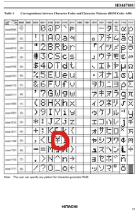
One of the cool features of the HD44780 type displays is their ability to display compose characters, or CG characters. You can compose up to 8 arbitrary different 5×7 patterns, store the patterns in RAM, and access them just like regular characters. This is helpful, because, well, the character set is a little weird – having some kind of foreign symbol where backslash should be, value 0x5C – see below.
HC44780 character set with foreign symbol where backslash should be
It can also be cool for creating industry-specific compose characters too. For instance, my first exposure to the HD44780 was in the late ’80s, where we designed it into the Kodiak Scoretec scoreboard system (I developed the electronics for the remote keyboard assembly, eventually became responsible for support of the entire system). It had little numbers for periods, number of fouls, a little football for possession, special characters for bonus etc.
Extend… CG Palette
The LCD library has the concept of a CG palette. There are far more than 8 compose characters defined, but only 8 can be used at any given time. When this library tries to display a CG character, it checks to see if it’s already in the palette. If it is, it uses it. If it is not, it finds an available CG location, loads it with the desired CG character, and uses it. If there are no CG locations available, it displays a question mark ‘?’.
I added a function to this, so that if no CG locations are available, every present CG character is cross checked to every character in the display RAM, to see if that CG character is presently in use. The first CG location that’s not in use, is removed to make room for the new CG character. At the end, if there just aren’t enough CG locations, again a question mark ‘?’ is displayed.
Extinguish… Backlight and Display Clear
I changed the clear() function to use the direct clear command, instead of writing spaces out to the screen. Much faster!
I also added a function to control the backlight, seeing as it can be turned on and off using I2C.
Speed, Speed… Always Need More Speed!
It turns out that accessing the display through I2C is quite slow. Now, I found a few easy things to speed things up… and there may be places where I can save time, but are more complex. However, those may be for a later time.
I modified the library to check whether a character is already in the display, before writing it out. If it is already there, it skips the write, saving precious I/O time.
Compared to the I/O time, the processor time is nothing, so this speeds things up considerably, especially if very little changes from second to second… like maybe, in an IRIG-B decoder display, hmmmmmm?
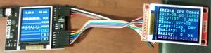
SPI 128 x 160 display operating with SPIDriver on output from read_irig program
I bought a cool device called SPIDriver through CrowdSupply. Actually, I bought two – and got them each with a neat little SPI based 132 x 162 colour LCD display.
It’s a very neat device, appearing as a USB serial port to your system. On my LINUX system, it appears as /dev/ttyUSBn. There are several sample programs and libraries available to drive SPIDriver, including for the display.
The display operates with a Sitronix ST7735 controller – here are a couple of different version datasheets: ST7735ST7735S_v1.1 .
Anyway, I hacked the included Python program st7735s.py to do my own bidding. irig_to_st7735.py takes STDIN text, uses the PIL library to rasterize it into graphics, and paints it into the little display.
Unfortunately, it takes about 1-1/2 seconds to get it transferred onto the display – it is a full graphics display, and it is a SPI interface, after all. I added an option to read_irig to put out 8 lines of text every 2 seconds, which I then piped into the Python program. It worked fine. Not terribly useful, but fine 🙂
#!/usr/bin/env python3
# coding=utf-8

#***************
# Import functions.
#---------------
import array
import getopt
import struct
import sys
import time

from PIL import Image, ImageDraw, ImageFont
from spidriver import SPIDriver

#***************
# Constants.
#---------------
Version			= 0
Issue			= 3
IssueDate		= "2019-05-06"
DefaultDevice	= "/dev/ttyUSB0"

LightBlue	= (102, 255, 255)
PaleBlue	= (102, 204, 255)
Red			= (255,   0,   0)
Yellow		= (255, 255,   0)
Lime		= (  0, 255,   0)
White		= (255, 255, 255)

NOP = 0x00
SWRESET = 0x01
RDDID = 0x04
RDDST = 0x09

SLPIN = 0x10
SLPOUT = 0x11
PTLON = 0x12
NORON = 0x13

INVOFF = 0x20
INVON = 0x21
DISPOFF = 0x28
DISPON = 0x29
CASET = 0x2A
RASET = 0x2B
RAMWR = 0x2C
RAMRD = 0x2E

PTLAR = 0x30
COLMOD = 0x3A
MADCTL = 0x36

FRMCTR1 = 0xB1
FRMCTR2 = 0xB2
FRMCTR3 = 0xB3
INVCTR = 0xB4
DISSET5 = 0xB6

PWCTR1 = 0xC0
PWCTR2 = 0xC1
PWCTR3 = 0xC2
PWCTR4 = 0xC3
PWCTR5 = 0xC4
VMCTR1 = 0xC5

RDID1 = 0xDA
RDID2 = 0xDB
RDID3 = 0xDC
RDID4 = 0xDD

PWCTR6 = 0xFC

GMCTRP1 = 0xE0
GMCTRN1 = 0xE1

DELAY = 0x80


#***************
# Pure Python rgb to 565 encoder for portablity
#---------------
def as565(ProcessedImage):
	#print ("ProcessedImage:", ProcessedImage)

	OriginalRed, OriginalGreen, OriginalBlue = [list(c.getdata()) for c in ProcessedImage.convert("RGB").split()]

	def MultiplyAndShift(ColourValue, ShiftBy):
		return ColourValue * (2 ** ShiftBy - 1) // 255

	d565 = [(MultiplyAndShift(BlueValue, 5) << 11) | (MultiplyAndShift(GreenValue, 6) << 5) | MultiplyAndShift(RedValue, 5) for (RedValue, GreenValue, BlueValue) in zip(OriginalRed, OriginalGreen, OriginalBlue)]

	d565h = array.array('H', d565)
	#print ("d565h:", d565h)
	d565h.byteswap()
	d565s = d565h.tostring()
	#print ("d565s:", d565s);
	return array.array('B', d565s)

def debug565(OriginalColour):
	print ("OriginalColour:", OriginalColour)

	OriginalRed, OriginalGreen, OriginalBlue = OriginalColour

	def MultiplyAndShift(ColourValue, ShiftBy):
		return ColourValue * (2 ** ShiftBy - 1) // 255

	d565 = [(MultiplyAndShift(OriginalBlue, 5) << 11) | (MultiplyAndShift(OriginalGreen, 6) << 5) | MultiplyAndShift(OriginalRed, 5)]

	d565h = array.array('H', d565)
	print ("d565h:", d565h)
	d565h.byteswap()
	d565s = d565h.tostring()
	print ("d565s:", d565s);
	return array.array('B', d565s)

#***************
# Class for wrangling with the ST7735 160 x 128 dot display
#---------------
class ST7735:
	def __init__(self, sd):
		self.sd = sd
		self.sd.unsel()

	def write(self, a, c):
		self.sd.seta(a)
		self.sd.sel()
		self.sd.write(c)
		self.sd.unsel()

	def writeCommand(self, cc):
		self.write(0, struct.pack("B", cc))

	def writeData(self, c):
		self.write(1, c)

	def writeData1(self, cc):
		self.writeData(struct.pack("B", cc))

	def cmd(self, cc, args=()):
		self.writeCommand(cc)
		n = len(args)
		if n != 0:
			self.writeData(struct.pack(str(n) + "B", *args))

	def setAddrWindow(self, x0, y0, x1, y1):
		self.writeCommand(CASET)  # Column addr set
		self.writeData(struct.pack(">HH", x0, x1))
		self.writeCommand(RASET)  # Row addr set
		self.writeData(struct.pack(">HH", y0, y1))
		self.writeCommand(RAMWR)  # write to RAM

	def rect(self, x, y, w, h, color):
		self.setAddrWindow(x, y, x + w - 1, y + h - 1)
		self.writeData(w * h * struct.pack(">H", color))

	def start(self):
		self.sd.setb(0)
		time.sleep(.001)
		self.sd.setb(1)
		time.sleep(.001)

		self.cmd(SWRESET)   # Software reset, 0 args, w/delay
		time.sleep(.180)
		self.cmd(SLPOUT)    # Out of sleep mode, 0 args, w/delay
		time.sleep(.180)

		commands = [
			(FRMCTR1, (     # Frame rate ctrl - normal mode
				0x01, 0x2C, 0x2D)),  # Rate = fosc/(1x2+40) * (LINE+2C+2D)
			(FRMCTR2, (     # Frame rate control - idle mode
				0x01, 0x2C, 0x2D)),  # Rate = fosc/(1x2+40) * (LINE+2C+2D)
			(FRMCTR3, (     # Frame rate ctrl - partial mode
				0x01, 0x2C, 0x2D,  # Dot inversion mode
				0x01, 0x2C, 0x2D)),  # Line inversion mode
			(PWCTR1, (      # Power control
				0xA2,
				0x02,       # -4.6V
				0x84)),     # AUTO mode
			(PWCTR2, (      # Power control
				0xC5,)),    # VGH25 = 2.4C VGSEL = -10 VGH = 3 * AVDD
			(PWCTR3, (      # Power control
				0x0A,       # Opamp current small
				0x00)),     # Boost frequency
			(PWCTR4, (      # Power control
				0x8A,       # BCLK/2, Opamp current small & Medium low
				0x2A)),
			(PWCTR5, (      # Power control
				0x8A, 0xEE)),
			(VMCTR1, (      # VCOM control
				0x0E,)),
			(MADCTL, (      # Memory access control (directions)
				0xC8,)),    # row addr/col addr, bottom to top refresh
			(COLMOD, (      # set color mode
				0x05,)),    # 16-bit color
			(GMCTRP1, (     # Gamma + polarity Correction Characterstics
				0x02, 0x1c, 0x07, 0x12,
				0x37, 0x32, 0x29, 0x2d,
				0x29, 0x25, 0x2B, 0x39,
				0x00, 0x01, 0x03, 0x10)),
			(GMCTRN1, (     # Gamma - polarity Correction Characterstics
				0x03, 0x1d, 0x07, 0x06,
				0x2E, 0x2C, 0x29, 0x2D,
				0x2E, 0x2E, 0x37, 0x3F,
				0x00, 0x00, 0x02, 0x10)),
			(NORON, ()),    # Normal display on
			(DISPON, ()),   # Main screen turn on
		]
		for c, args in commands:
			self.cmd(c, args)

	def clear(self):
		self.rect(0, 0, 128, 160, 0x0000)

	def writestrings(self, ListOfLineStrings):
		#print ("On entry into writestrings(), ListOfLineStrings: ", ListOfLineStrings)

		#print ("Starting writestrings")
		BaseWidth  = 160
		BaseHeight = 128

		# make a blank image for the text, initialized to transparent text color
		TextImage = Image.new('RGB', (BaseWidth, BaseHeight), ( 16,  16,  16))

		TextSize = int(BaseHeight/ 8)
		LineColours = (White, Lime, Lime, PaleBlue, LightBlue, LightBlue, Yellow, Red)
		#print ("Length of list of LineColours: " + "{0:d}".format(len(LineColours)))
		StartColumnOffset = 0

		# get a font
		#FontToWrite = ImageFont.truetype('Pillow/Tests/fonts/FreeMono.ttf', int(TextSize))
		FontToWrite = ImageFont.truetype('Courier_New.ttf', int(TextSize))
		# get a drawing context
		DrawContext = ImageDraw.Draw(TextImage)

		# draw text, full opacity
		LineNumber = 1
		for LineString in ListOfLineStrings:
			#print ("LineString: " + LineString)
			if  (LineNumber > len(LineColours)):
				print ("Past end of colour list, LineNumber = " + "{0:d}".format(LineNumber) + " and length of LineColours list = " + "{0:d}".format(len(LineColours)))
				print ("Length of ListOfLineStrings = " + "{0:d}".format(len(ListOfLineStrings)))
				print ("ListOfLineStrings: ", ListOfLineStrings )
				print ()
				LocalColour = White
			else:
				LocalColour = LineColours[LineNumber-1]

			DrawContext.text((StartColumnOffset, (LineNumber-1)*TextSize), LineString, font=FontToWrite, fill=LocalColour)
			LineNumber += 1

		FinalImage = TextImage

		# debug by saving images to disk
		#print ("Output 01txt.jpg")
		#SaveImage = TextImage.convert('RGB')
		#SaveImage.save("01text.jpg")

		#print ("Ouput 02base.jpg")
		#SaveImage = BaseImage.convert('RGB')
		#SaveImage.save("02base.jpg")

		#print ("Ouput 03final.jpg")
		#SaveImage = FinalImage.convert('RGB')
		#SaveImage.save("03final.jpg")


		#print ("FinalImage.size")
		#print (FinalImage.size)

		if FinalImage.size[0] > FinalImage.size[1]:
			#print ("Rotating 90 degrees")
			FinalImage = FinalImage.transpose(Image.ROTATE_90)
		#w = 160 * FinalImage.size[0] // FinalImage.size[1]
		#FinalImage = FinalImage.resize((w, 160), Image.ANTIALIAS)
		#(w, h) = FinalImage.size
		#if w > 128:
			#FinalImage = FinalImage.crop((w // 2 - 64, 0, w // 2 + 64, 160))
		#elif w < 128:
			#c = Image.new("RGB", (128, 160))
			#c.paste(FinalImage, (64 - w // 2, 0))
			#FinalImage = c
		st.setAddrWindow(0, 0, 127, 159)
		#st.writeData(as565(FinalImage.convert("RGB")))
		st.writeData(as565(FinalImage))


#***************
# Function to provide usage help.
#---------------
def usage():
		print ("\nTake in read_irig LCD output and display to ST7735 display attached to SPIDriver, v"+"%1d" % (Version)+"."+"%1d" % (Issue)+" "+IssueDate+" dmw")
		print ("\nTypical usage: "+sys.argv[0]+" [option]* ")
		print ("\n      Options: ")
		print   ("               -o <device>           Output device for SPIDriver (default " + DefaultDevice + ")")
		print   ("               -v                    More verbose")

		print ("\n      RCS Info:")
		print   ("               Header: /home/dmw/src/ntp/refclock_irig/RCS/irig_to_st7735.py,v 1.4 2019/05/17 03:37:27 dmw Exp")

		print ("\n")


#***************
# Main function.
#---------------
if __name__ == '__main__':
	#***************
	# Get command line options.  Error results in help text dump and exit.
	#---------------
	try:
		opts, args = getopt.getopt(sys.argv[1:], "o:v")
	except getopt.GetoptError as Error:
		# print help information and exit:
		print ("\n")
		print (Error) # will print something like "option -a not recognized"
		print ("\n------------------------------")
		usage()
		sys.exit(2)

	#***************
	# Set defaults.
	#---------------
	UseDevice	= DefaultDevice
	Verbose		= False

	#print ("Checking options now")

	#***************
	# Parse values from command line options.  Error results in message and exit.
	#---------------
	for Option, Argument in opts:
		#print ("Checking option: " + Option + ", with argument: " + Argument)
		if   Option in ("-o"):              # Output file name.
			UseDevice = Argument
			#print ("\nUsing device: " + UseDevice)
		elif Option in ("-v"):              # Turn on verbosity.
			Verbose = True
		else:
			print ("\nUnknown option \"" + Option + " " + Argument + "\", aborting...")
			print ("\n------------------------------")
			usage()
			sys.exit(2)

	if  (Verbose):
		print("\nLightBlue")
		debug565(LightBlue)

		print("\nPaleBlue")
		debug565(PaleBlue)

		print("\nRed")
		debug565(Red)

		print("\nYellow")
		debug565(Yellow)

		print("\nLime")
		debug565(Lime)

		print ("\nWhite")
		debug565(White)

		print ()
		print ("\nUsing device: " + UseDevice)

		print ()

	#exit(0)

	#***************
	# Open ST7735 display through SPIDriver, initialize and clear.
	#---------------
	st = ST7735(SPIDriver(UseDevice))
	st.start()
	st.clear()

	#***************
	# Initial message.
	#---------------
	LineList = [
		#         1111111
		#1234567890123456
		"  IRIG Decoder",
		"v"+"%1d" % (Version)+"."+"%1d" % (Issue)+" "+IssueDate,
		"    (c) 2019",
		"  Dean Weiten",
		"  Winnipeg, MB",
		" (204)-888-1334",
		" dmw@weiten.com"]
	st.writestrings( LineList )

	#***************
	# Loop on input.
	# Expecting up to 8 lines per frame,
	# up to 16 characters per line.
	# Colours are fixed sequence.
	# An exception (often a ctrl-C break)
	# results in clearing and exit message display.
	#---------------
	try:
		LineIndex = 0
		LineList = []
		for line in sys.stdin:
			FindFF = line.find('\f')
			if  (FindFF>=0):
				if  (Verbose):
					print ("Got FF at " + "{0:d}".format(FindFF))
					print( "The line up to the FF is \"" + line[:FindFF] + "\"." )

				LineToAppend = line[:FindFF].rstrip("\r\n\f")
				if  (len(LineToAppend) > 0):
					LineList.append(LineToAppend)
				st.writestrings( LineList )
				LineList = []
				LineToAppend = line[FindFF+1:].rstrip("\r\n\f")
				if  (len(LineToAppend) > 0):
					#print ("First line \"" + LineToAppend + "\" has length " + "{0:d}".format(len(LineToAppend)) + ", so will be appended, list is at present: \"", LineList, "\".")
					LineList.append(LineToAppend)
			else:
				LineToAppend = line.rstrip("\r\n\f")
				if  (len(LineToAppend) > 0):
					#print ("Line \"" + LineToAppend + "\" has length " + "{0:d}".format(len(LineToAppend)) + ", so will be appended.")
					LineList.append(LineToAppend)
					#print ("Length of LineList after append is " + "{0:d}".format(len(LineList)) + ".")

			if  (Verbose):
				print( "The line list is:" )
				print(LineList)
			#st.writestrings(LoopNumber)
			#LoopNumber += 1

	finally:
		st.clear()

		#time.sleep(3)

		LineList = [
			#         1111111
			#1234567890123456
			"  IRIG Decoder",
			"v"+"%1d" % (Version)+"."+"%1d" % (Issue)+" "+IssueDate,
			"",
			"    Exiting"]
		st.writestrings( LineList )

		time.sleep(4)

		st.clear()